-
Posts
451 -
Joined
-
Last visited
-
Days Won
23
HarryA last won the day on February 15
HarryA had the most liked content!
About HarryA
- Birthday June 23
Profile Information
-
Gender
Male
-
Location
USA, Pennsylvania, Susquehanna County,
-
Interests
Canoeing, woodworking, electronics, and gardening.
Recent Profile Visitors
The recent visitors block is disabled and is not being shown to other users.
HarryA's Achievements
-

MOSFET Power module and gate drive connections guidance
HarryA replied to mumartahir's topic in Power Electronics
You can get technical support here: https://www.monolithicpower.com/en/products/ev1909-tl-00a.html -
Promac TV Universal Remote Codes & Program Instructions
-
 KieranBlackburn reacted to a post in a topic:
seven segment display 0,28 inch with 6 pins only / programming etc.
-

Automatic electric bell using wifi
HarryA replied to PS ADITHYAN's topic in Electronic Projects Design/Ideas
If you search on the internet for "Automatic electric bell using wifi "you will find numerous articles on the subject: like: https://www.youtube.com/watch?v=jkG9sUWc1CA -
 Maria Erick reacted to a post in a topic:
Except by doing physical projects, how can I make learning digital electronics fun?
-
lev jeysel started following HarryA
-

Dfplayer with Arduino pushbutton and led fading
HarryA replied to abhishek gyani's topic in Projects Q/A
What does not work? The LED fade or the mp3 player? What do you wish the push button to do? A: Push the button once and the LED fades on and off until you push it again. B: The LED fades on and off while you hold the button down. Releasing it the fading LED stops. -
abhishek gyani started following HarryA
-

Dfplayer with Arduino pushbutton and led fading
HarryA replied to abhishek gyani's topic in Projects Q/A
I am not sure what you need but here is code that fades a LED up and down. It does not block your code by using Delay(), You can paste it into your Loop{} or call it as a function. You may wish to play with the int period value and the +/-5 value. Do note which i/o pins you can use with this PWM code. //use pins 3, 5, 6, 9, 10, and 11 on the UNO const int ledPin = 3; //whichevery pin you choose Do not forget the resistor! int period = 10; //how fast to fade the LED:100 = 1/10 sec. etc unsigned long time_now = 0; //have not read the time yet int brightness = 0; //start with LED off boolean IncreaseBrightness = true; //start with increasing brightness void setup() { pinMode(ledPin, OUTPUT); Serial.begin(9600); //you may have this; used here for testing } void loop() { // non-blocking delay if(millis() > time_now + period) //get current time and compare { time_now = millis(); //for next time //fade LED up or down if(IncreaseBrightness) { analogWrite(ledPin, brightness +=5 ); if(brightness >= 255) IncreaseBrightness = false; //max ouput to LED = 255 } else //must be decreasing brightness { analogWrite(ledPin, brightness -=5 ); if(brightness <= 0 ) IncreaseBrightness = true; //min ouput to LED = 0 } } //some code...testing displays values..... Serial.print("brightness "); Serial.println(brightness); } -

Guitar feedback issue at high frequencies - please help
HarryA replied to Sam_sky's topic in Electronics chit chat
I prototyped a couple of passive notch filter circuits including the one Tony posted. But neither were very good; two broad. If I can find an inductor between 150 to 200 mh I will try a parallel resonant band stop filter. This site maybe helpful: 8 Ways Of Resolving The Electric Guitar Feedback Problem -

Guitar feedback issue at high frequencies - please help
HarryA replied to Sam_sky's topic in Electronics chit chat
What you need is a notch filter to remove only a narrow band of unwanted frequencies . There are pedal notch filters on the market but they are pricey. Search on "guitar notch filter pedal". Also see:: https://lambdageeks.com/notch-filter/#:~:text=A notch filter%2C also known as a frequency,while allowing other frequencies to pass through unaffected. About half way down the page he covers guitar pedals. If you wish to make one perhaps I could help you with it. -
It looks good to me. I would go with it. Are you building something interesting?
-
Perhaps you could convert the alternator output directly to dc without a transformer to 300vdc (or about) and use a 127-350 dc to 24 v dc dc/dc converter to get 24 volts. See: DC/DC converter 250V to 24V, 960W
-
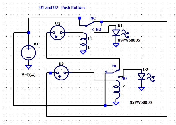
I do not see the connections to relay's NC contacts for each LED. The red LED most get its current through the NC contacts of the Green LED's relay. And the green LED must get its current through the NC contacts of the red LED's relay. Thus when one relay is active the other LED can not receive current through the the now open NC contacts.


