Simple LC meter
- Hristo
- xristost@yahoo.com
- 107.394 Views
- medium
- Tested
This project is a simple LC meter based on PIC16F682A mcu.
Description
Here is another piece of laboratory equipment – LC meter. This type of meter, especially L meter is hard to find in cheap commercial multimeters.
Schematic of this one came from this web page:https://sites.google.com/site/vk3bhr/home/index2-html.
It uses PIC microcontroller 16F628A, and because I recently acquired a PIC programmer, I decided to test it with this project. Following the above link you will find the original schematic, PCB, source and HEX files for programing the microcontroller and detailed description.
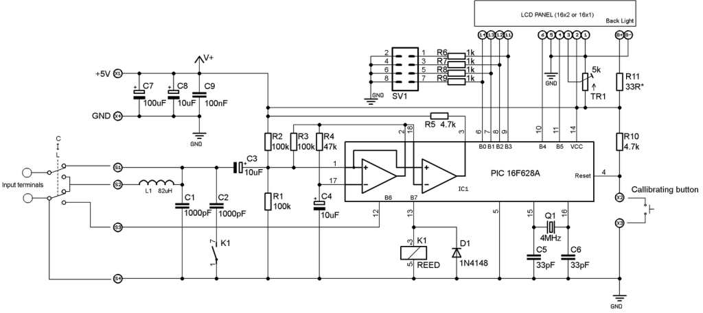
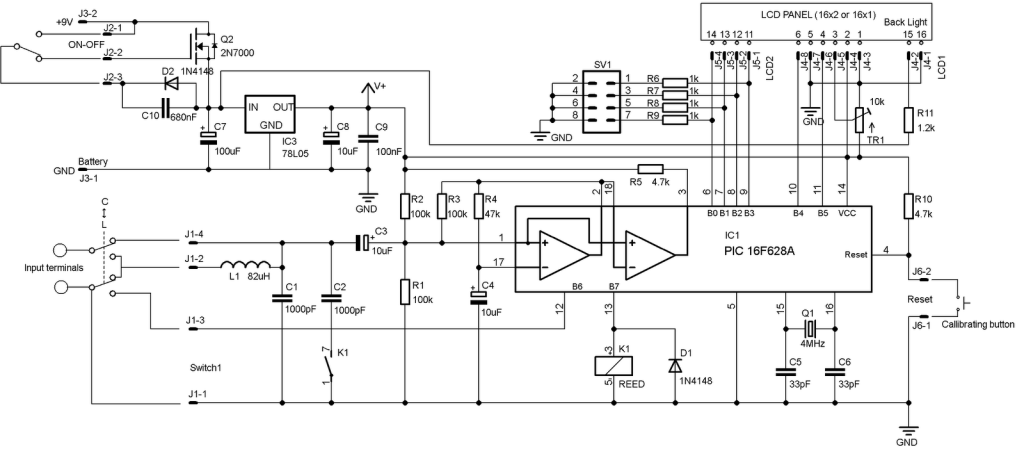
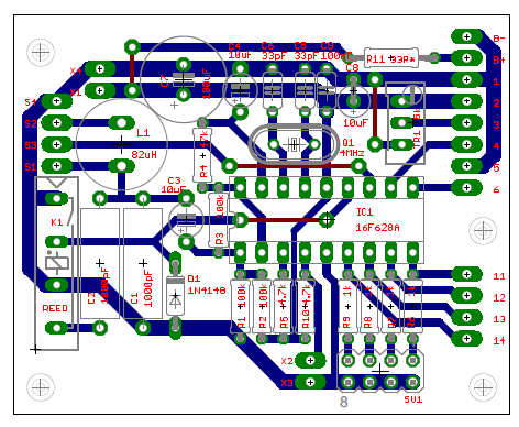
Here is my adaptation of the schematic:
I removed the 7805 regulator, because I decided to use a 5V adapter from Sony mobile phone.
In the schematic, trimmer-potentiometer is 5k, but actually I put 10k, after consulting with the datasheet of the LCD module I bought. All three 10uF capacitors are tantalum and C7 – 100uF actually is 1000uF. Two 1000pF capacitors are styroflex 1% and inductor is 82uH. Total consumption (with back light) of the device is 30mA.
R11 limits the back light current and must be calculated according to the actual LCD module used.
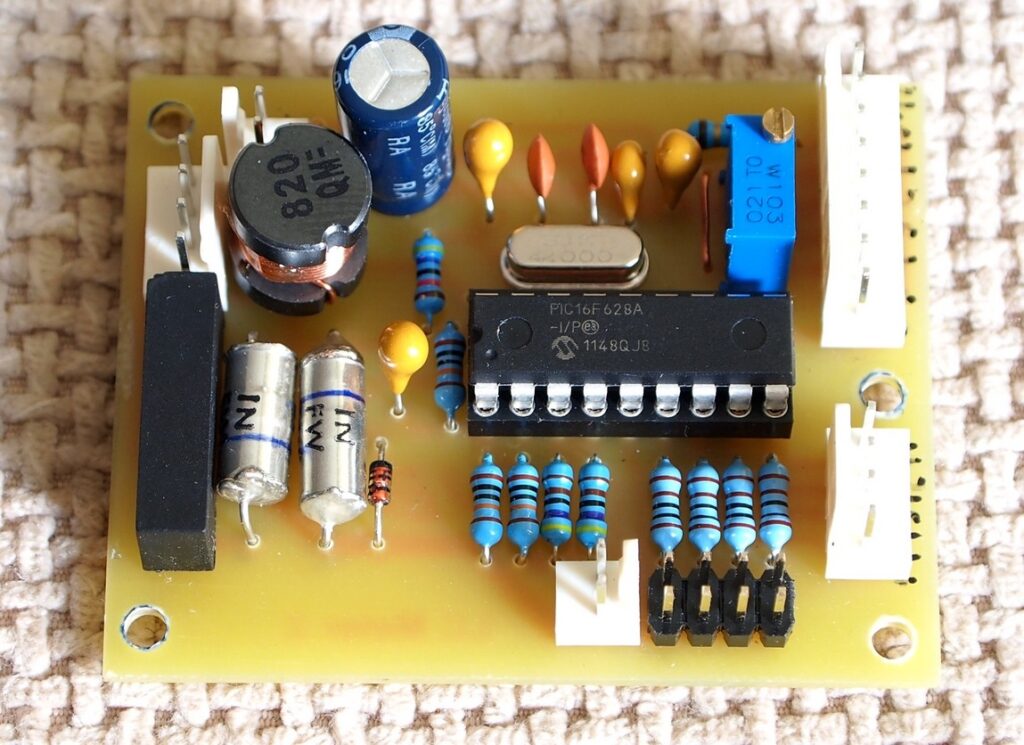
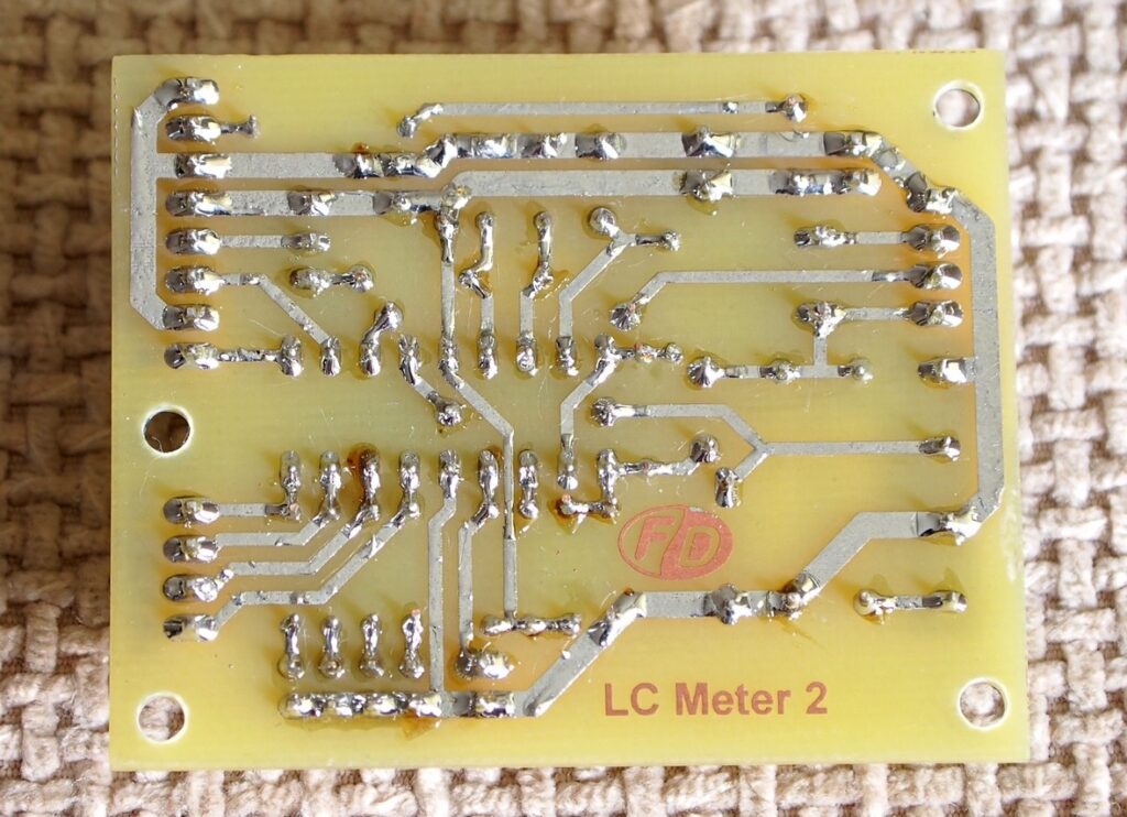
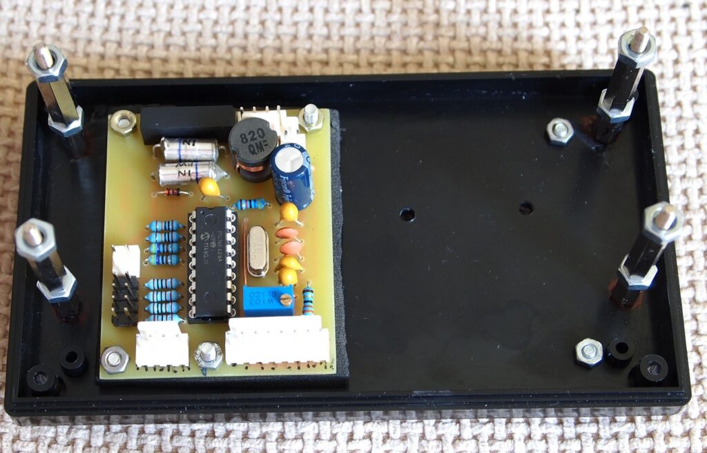
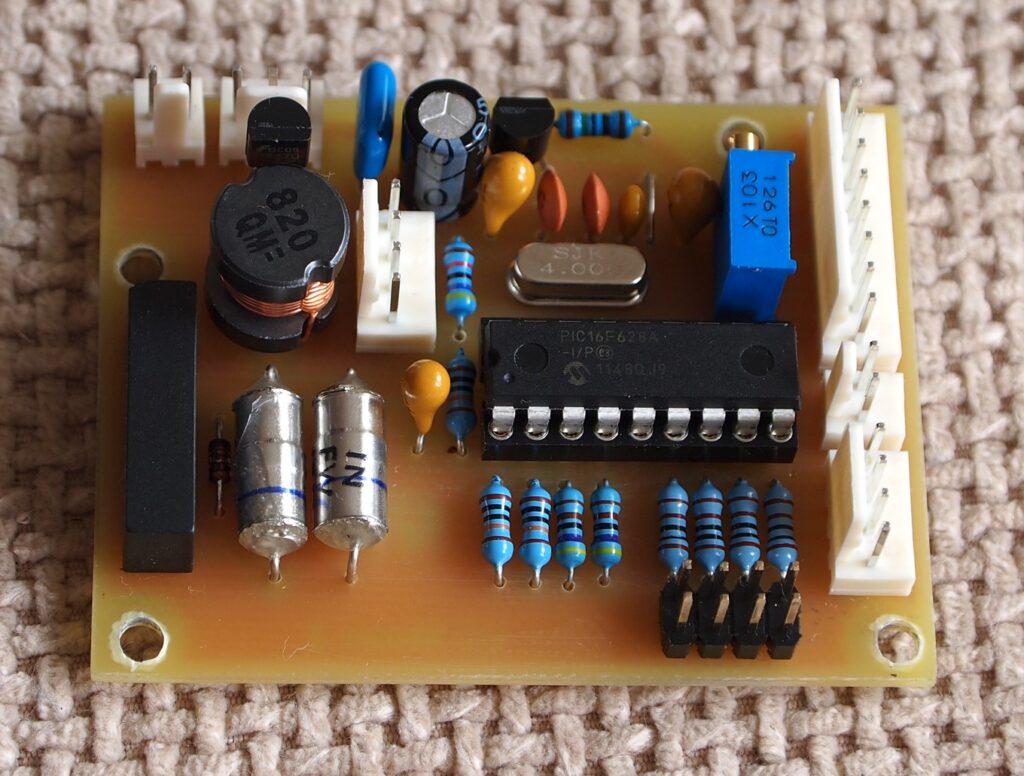
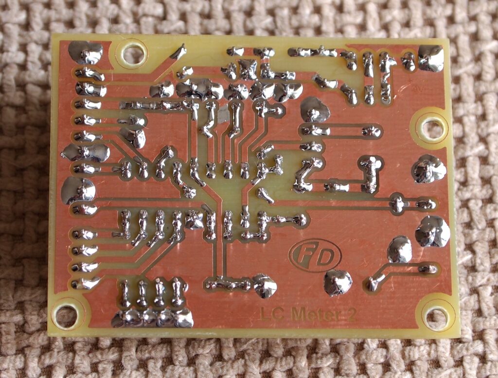
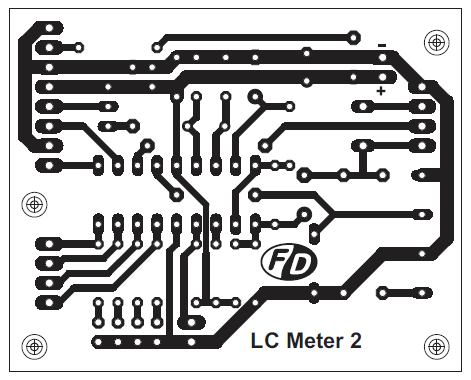
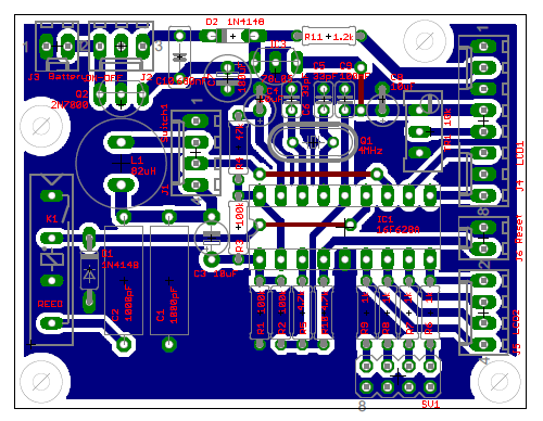
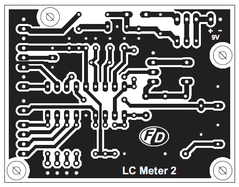
I used the original PCB as a starting point and modified it to suit better to my components.
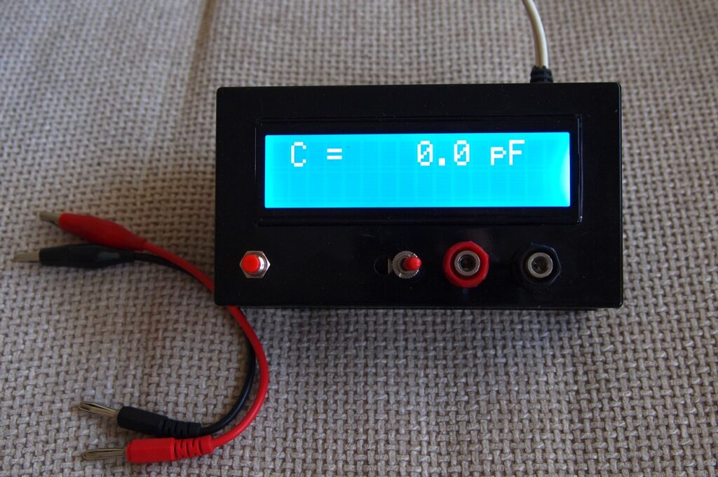
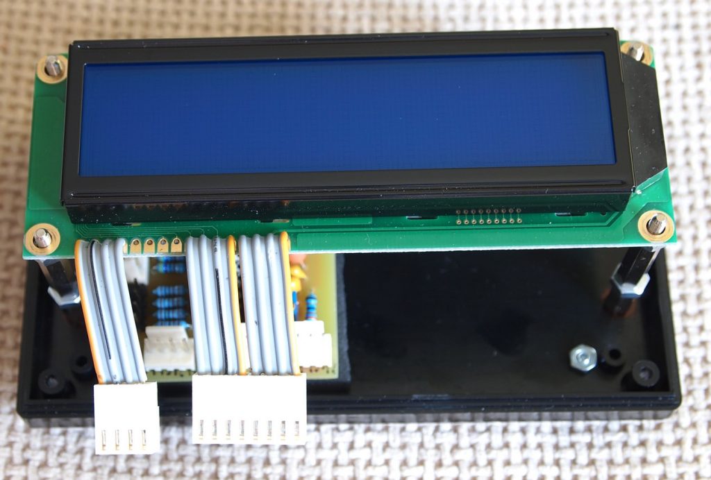
Here is the result:
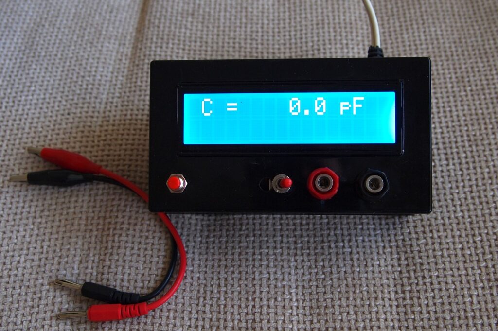
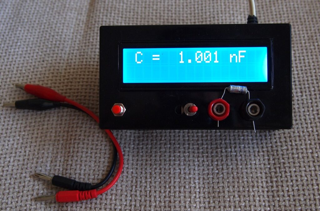
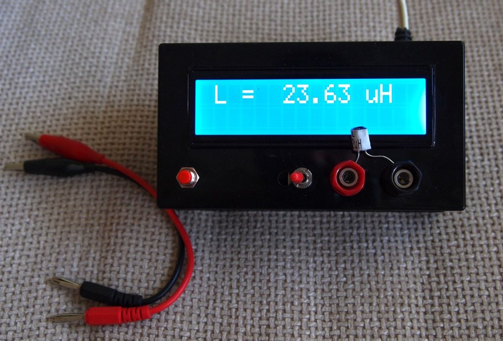
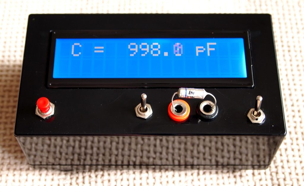
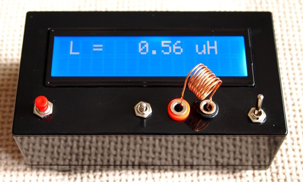
The last two pictures shows LC meter in action. In the first of them, there is 1nF/1% capacitor and in the second – 22uH/10% inductor. The device is very sensitive – when I put the test leads there is 3-5 pF reading on display, but it is eliminated with the calibrating button.
Schematic
Photos
Update: 24 June 2012
One of my colleagues in a Bulgarian audio forum ask me to build him a copy of the LC meter, but this time with 9V battery power supply. I made a new PCB with little rearrangement of the old one and adding a 78L05 voltage regulator.
I also added an automatic sleep mode, schematic of which I found here:http://www.marc.org.au/marc_proj_switch.html
The goal here was to make power consumption as low as possible. With increasing the value of R11 to 1.2kOhm which control the back light current, total current of the device was decreased to 11-12mA. Without back light at all the power consumption will be decreased even further, but the visibility suffers greatly.
After some tests, the value of the C10, which defines the ON time, was chosen to be 680nF. The ON time in this case is 10-11 min. The MOSFET Q2 may be replaced with BS170, but bear in mind that the leads are in reverse order.
ON-OFF switch is momentary non lock type.




Where is the code or hex file for PIC 16F628A ???
You should find it on the original project link here: https://sites.google.com/site/vk3bhr/home/index2-html
Where is the code or hex file for PIC 16F628A ???
sent to hex file email adress : phongk8a1@gmail.com
thank
please provide the proteus file
Sorry, Proteus file isn’t available.
I made the circuit in proteus and LCD shows calibrating…..(No change after that )
share the Project, please!
Could you send me the Proteus file please? Thanks in advance
t90nassa@gmail.com
Hex code .,?? kiral96@hotmail.com upload
Hex code is added on the downloads section above.
Muchas gracias amigo. Espero que funcione. Te volveré a escribir si consigo terminarlo. Soy nuevo en esto de la electrónica. Un saludo.
Thank you very much, my friend. Hope it works. I’ll write again if I can finish it. I am new in electronics. A greeting.
This meter works good with capacitors. When I switch it to inductors it shows me ‘overrange’ . Then I insert inductor and it shows it’s inductance correctly. Something wrong with my device or this is correct behaviour ? Thanks
It seems correct behavior to me. But it’s better to contact the author about it.
is the hex file works same on other L c meter circuit ??
You need to burn the specific .hex file to PIC mcu
The reed you use is replay? How many pin does it have? In Schematic I see It has 2 pins. But, anyway I has 4 pins in PCB, what’s wrong?
The reed relay K1 controls switch K1, so actually it has 4 pins.
I need the code (maybe wirted .txt not .hex) Where I can find it?
Sir is reed relay a solid state relay
No, reed relay is a relay that uses magnetic field to control it’s state.
I had success using a reed relay 5V, SIP 1A05 (Pan-Chang) from eBay.
what did you do with two other relay legs
You just have to connect the coil contacts and the Normal Open contacts. No other connections are needed.
excuse me sir please help me, what is reed relay in this circuit ??? please say all of specification. thanks
A reed relay used in this project is something like this: https://www.bc-robotics.com/shop/5v-reed-relay-spst-no/
hi friend please say me about reed relay in this project.why use it.? can another thing replace it.?
can we use 82uh resistor like inductor ?
no you can’t use a resistor in place of an inductor. You can use an inductor of 82uH that may look like a resistor from the outside.
sorry for my English. i tried to say can we use 82uh inductor looks like a resistor.
as i understand from your reply i can use it right?
thank you very much
Yes, an inductor can look like a resistor.
I am looking for an LR schematic, I would like to measure speaker resistance at selectable frequencies. Can anyone asssit?
I made it but just show me over range and i did everything that said in lc meter v2 page but nothing get fixed: ( f1 and f2 just show me 00000001 my relay works fine i dont know what should i do. pls pls pls help me i really need it asap dudes
hi, does it work with other PIC microcontroller? I have pic16f688 will the hex file upload.
thanks
Hi, is there chance to get .brd and .sch file ?