Simple Crystal Tester
- Izhar Fareed
- http://www.extremecircuits.net
- izhar@gmx.us
- 28.417 Views
- Non tested
Description
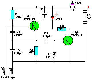
Transistor Q1, a 2N3563, and its associated components form an oscillator circuit that will oscillate if, and only if, a good crystal is connected to the test clips. The output from the oscillator is then rectified by the 1N4148 signal diode and filtered by C3, a 100pF capacitor. The positive voltage developed across the capacitor is applied to the base of Q2, another 2N3563, causing it to conduct.
When that happens, current flows through Led1, causing it to glow. Since only a good crystal will oscillate, a glowing LED indicates that the crystal is indeed OK. You can use the NTE123AP, PN100, or the 2N3904, for the transistors, however, the circuit works better with the 2N3563’s for crystals in the higher MHz. The NTE108 is a direct replacement for the 2N3563. R3, the 330 ohm resistor for the Led, can be lowered to 220/270 ohm if your application is for crystals in the high MHz, which makes the led glow dimly in some instances. The circuit is powered by a standard 9-volt battery and the SPST push button power-switch is included to prolong battery life but not really needed if you use a socket for the crystal-under-test. I’m using this particular simle tester myself.
Parts List
- R1 = 100K C1,C2 = 220pF
- R2 = 2K2 C3 = 100pF
- R3 = 330 Ohm C4 = 0.1uF (100 nF)
- Q1,Q2 = 2N3563 D2 = red led, ultra-bright
- D1 = 1N4148 S1 = Momentary Push-button, SPST (optional)
Miscellaneous: crocodile clips (or others), 9V battery clip, wire, solder, etc


