60V input to 5V – 3A output DC-DC Converter for Industrial and Automotive using TPS54360
- Rajkumar Sharma
- 15.659 Views
- easy
- Tested
- SKU: EL70937
- Quote Now
This is a 60 V 3A step down DC-DC converter. Sample applications are: 12 V, 24 V and 48 V Industrial, Automotive and Communications Power Systems. The TPS54360 is a 60 V, 3 A, step down regulator with an integrated high side MOSFET. The device survives load dump pulses up to 65V per ISO 7637. Current mode control provides simple external compensation and flexible component selection. A low ripple pulse skip mode reduces the no load supply current to 146 μA. Shutdown supply current is reduced to 2 μA when the enable pin is pulled low. Under voltage lockout is internally set at 4.3 V but can be increased using the enable pin. The output voltage start up ramp is internally controlled to provide a controlled start up and eliminate overshoot. A wide switching frequency range allows either efficiency or external component size to be optimized. Frequency fold back and thermal shutdown protects internal and external components during an overload condition.
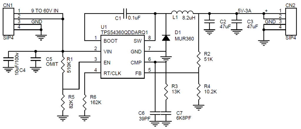
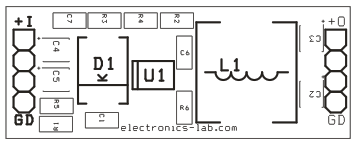
Note: The output voltage is set by a resistor divider from the output node to the FB terminal. It is recommended to use 1% tolerance or better divider resistors, choose R2, R4 for other output voltage.
Features
- Supply Input 9V-60V
- Output 5V (Output Voltage adjustable with R2, R4)
- Output Current 3A
- Current Mode Control DC-DC Converter
- High Efficiency at Light Loads with Pulse Skipping Eco-mode™
- Low Dropout at Light Loads with Integrated BOOT Recharge FET
- 146 μA Operating Quiescent Current
- Internal Soft-Start
- Accurate Cycle-by-Cycle Current Limit
- Thermal, Overvoltage, and Frequency Fold back Protection
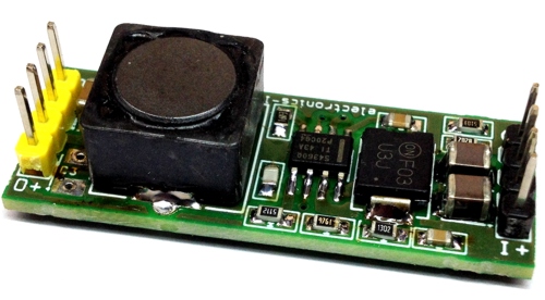
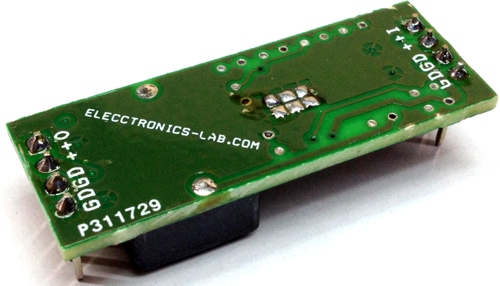
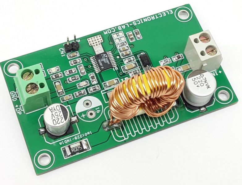
- PCB Dimensions 42.38mm x 16.21mm
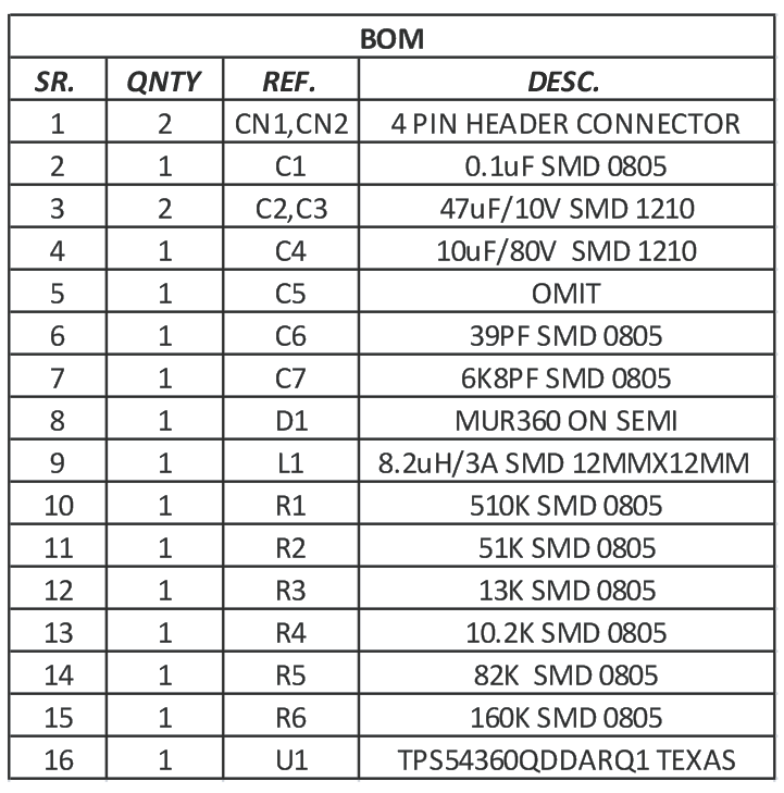
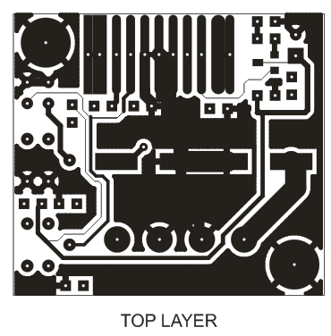
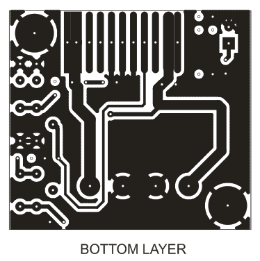
Schematic





Can I order this item to Bulgaria
We can produce and ship this board if quantity is over >25 pieces. Thanks
Hi How to order this?
We can manufacture this if order quantity is >25 pieces. If you are interested use the contact us form.
What is the value of R2 & R4 for 12v output?
Check paragraph 8.2.2.9 Output Voltage and Feedback Resistors Selection on datasheet on how to calculate these resistors.
In FEATURES paragraph there is change R3 & R4 for output voltage,but in paragraph 8.2.2.9 there is change R5 & R6 value.Kindly help me out with by choosing which resistors and there values for output voltage of 12v.
R5 from datasheet corresponds to R2 in our schematic and R6 -> R4 in our schematic. Hope it’s clear now
Does this work with three input of 5v considering the total load current of all the 3 output will be around 2.5A. Can i just add in parallel one more input