MSF Radio Time Clock
- Paul Qureshi
- paul@world3.net
- 23.211 Views
- medium
- Tested
Introduction
The National Physics Laboratory broadcasts a time signal, previously known as the Rugby clock but now called “Time from NPL.” Its most commonly known as the MSF signal due to it originally being identified in Morse code those letters. It is broadcast from Anthorn on 60kHz. Many commercial clocks use it to automatically set themselves.
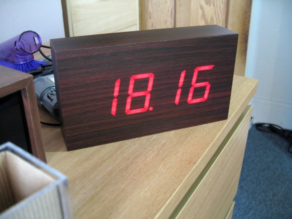
I decided to convert a digital clock I bought into one set by the MSF signal. To make the project more interesting I decided to use the ATtiny2313 microcontroller with only 2k flash ROM and 128 bytes of RAM.
Features:
- Automatically set by MSF time signal
- Bright, flicker free display
- Alarm with choice of 5 polyphonic melodies
- Hour chime with choice of melodies and no chime between 00:00 and 08:00
Hardware
The original clock electronics used two PCBs, one for the 7 segment LEDs and another for the clock controller and support hardware. I started by tracing the connections between them and mapping out how the display worked.
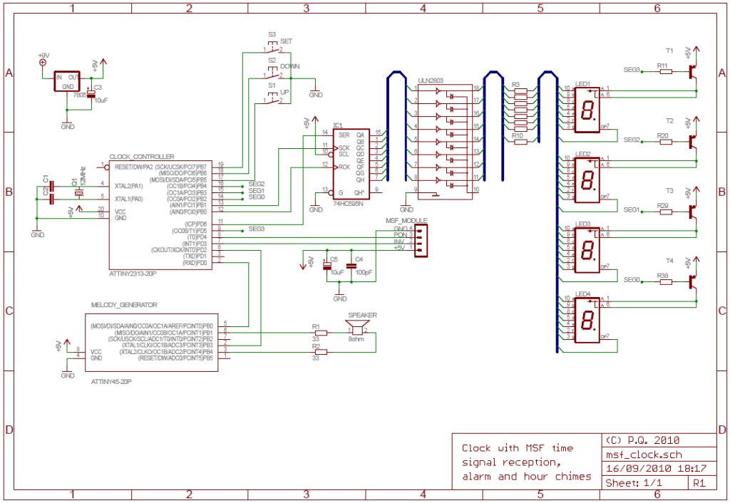
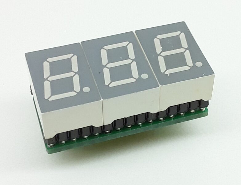
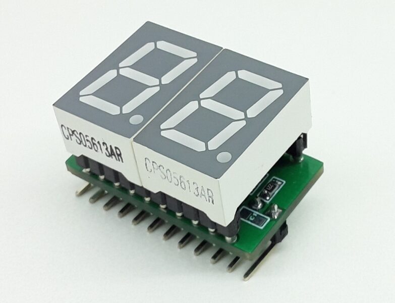
The display is multiplexed with simple transistor switches for the common anode. Only the middle two 7 segment displays have dots. I connected the anode transistors to the AVR with 2k2 resistors to limit current and the cathodes to a 74HC595 shift register via a ULN2803 Darlington array. I removed the controller IC and all other unused parts.
The AVR uses a 12MHz crystal which is accurate enough for keeping time. In my initial tests on the bench it varied by less than one second per day, but when installed in the clock case it looses about 3-4 seconds over 24 hours. Since the time is re-synchronised with the MSF signal every night that is more than adequate.
An MSF receiver module is connected to the AVR. I bought it for a few pounds and it works very well, although like most low frequency time code receivers it is extremely sensitive to noise. The multiplexed display has to be turned off while it is in use, so it is not possible to see the current time when it is being re-synchronised. I had to use a long USB cable for programming during development because the electrical noise from my PC was interfering.
Firmware
ATtiny2313 memory use summary [bytes]:
Segment   Begin    End      Code   Data   Used    Size   Use%
-------------------------------------------------------------
[.cseg] 0x000000 0x0007f8   2006     34   2040    2048  99.6%
[.dseg] 0x000060 0x000060      0      0      0     128   0.0%
[.eseg] 0x000000 0x000000      0      0      0     128   0.0%
Time keeping is via an interrupt that also handles display multiplexing. The display is multiplexed at 100Hz which translates to a 400Hz timer interrupt (4 digits x 100Hz). The interrupt also sends signals back to the main code when minutes and hours increment.
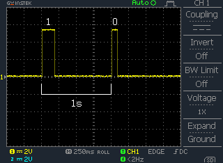
Oscilloscope trace of MSF signal
The MSF protocol represents binary bits with differing length pulses which are generated by switching the carrier signal on and off. The main two are 100ms (zero) and 200ms (one). The start of a minute is signaled with a 500ms pulse and towards the end of the minute cycle the parity bits can be 300ms long.
| MSF bit | Meaning | Format |
| 00 | Start of Minute Marker | 500ms pulse |
| 01..16 | DUT1 offset | |
| 17..24 | Year | 8 bit BCD 00..99 |
| 25..29 | Month | 5 bit BCD 01..12 |
| 30..35 | Day of Month | 6 bit BCD 01..31 |
| 36..38 | Day of Week | 3 bit BCD 1..7 |
| 39..44 | Hour | 6 bit BCD 00..23 |
| 45..51 | Minute | 7 bit BCD 00..59 |
| 52 | End of Minute Marker | Always 0 |
| 53 | BST change warning | 1 bit flag |
| 54 | Year Parity | Odd parity bits 17..24 |
| 55 | Month Parity | Odd parity bits 25..35 |
| 56 | Day of Week Parity | Odd parity bits 36..38 |
| 57 | Time Parity | Odd parity bits 39..51 |
| 58 | BST flag | 1 bit flag |
| 59 | Unused | Always 0 |
For details of the data format the Wikipedia page has some information about the signal which is mostly correct. The NPL documentation is also quite useful.
MSF reception requires fault tolerant code. Even under ideal conditions the signal is likely to contain noise. The decoded signal also has to be validated before being accepted.
The MSF reception routine waits for a pulse to start and then measures the length using a 100Hz timer. It rejects pulses (or drop-outs) of less than 5ms as noise. There is ±20ms leeway when decoding pulse lengths.
Once one complete minute’s worth of pluses have been received they are decoded, sanity checked and parity checked. If the signal looks valid then the decoded data is stored and a second signal is received. If that second signal also passes all checks and gives a time exactly one minute after the first then it is deemed correct and the clock synchronised.
Synchronisation takes place when the clock is first powered on and again at 3AM every night. 3AM was chosen to avoid inconveniencing the user and because there is less RF interference at night.
A note about MSF signal accuracy. The broadcast time is supposed to be within 1ms of UTC. However, there is propogation delay between the transmitter and the receiver which cannot easily be measured or removed automatically. Based on where I live I estimate the delay to be around 275ms. GPS time compensates for this delay.
User Interface
The clock is controlled by three buttons on the back. Since the clock uses the MSF signal to set itself automatically there is no way to set it manually. In any case there is not enough free flash memory to implement a time setting interface.
Holding down the SET button for one second enters setting mode. The UP/DOWN buttons change the setting and SET advances to the next one. The sequence is:
1. Alarm on/off
2. Alarm hour
3. Alarm minute
4. Alarm melody
5. Hour chime on/off
6. Hour chime melody
Buttons are debounced and repeat when held.
Melody Generator
I had planned to make the ATtiny2313 generate alarm melodies and hour chimes, but there was not enough code space left. I decided to modify ChaN’s Wavetable Melody Generator and control it with the 2313. ChaN is a bit of a genius when it comes to implementing things like this in an efficient yet flexible way with a minimum of external hardware required. In fact his WGM only requires an ATtiny45, speaker and power supply to work.
The requirements for the Melody Generator were multiple melodies and chimes. I decided to use music and sounds from Japan Rail (JR) stations. Probably only a 鉄道ファン, can understand why 🙂
I started by creating a new wavetable (actually there is only one instrument so it isn’t really a “table”…) using a sample from the default TiMidity++ set. It had to be cut into two sections, the attack and sustain phases. Typically instruments that are percussive (e.g. pianos, bells, chimes) create a sudden transient sound when hit where the waveforms are non-symmetrical called the attack. They then quickly start to oscillate and fade out as energy is lost, called the sustain. Because the oscillating part of the sound is simply the same waveform repeated with ever decreasing magnitude it is only necessary to store one cycle and reduce its amplitude to zero over the length of the sustain period. This method also makes it easy to vary the length of the sustain.
I found MIDI versions of the melodies and chines I wanted and converted them to text with MIDINOTE. The text was then imported into Excel, re-exported to text in a more suitable format and cleaned up in Notepad++. Finally ChaN’s Perl script was used to convert them to AVR assembler include files.
ChaN’s code was altered to support multiple scores, each with it’s own sustain decay rate. I also added some code to interface the ATtiny45 with the main ATtiny2313 using a very simple protocol. The 2313 pulls an enable line low and then pulses a data line a number of times corresponding to the score it wants to have played.
The hardware is trivial – merely an 8Ω speaker connected directly to the AVR.





The following project for (wavetable melody generator).
I ask you a code written in language c.
85, codevision attiny.
Don’t know how to use code attached asm.
Also, is behavior comes, but is too small. code attached hex
I wish to submit a clear, elegant sound.
I beg you.
Thank you very much.
Reply to this
The code must be compiled using an ATMEL compiler and burned on Attiny, or you can directly program you mcu using the .hex file. For more details please contact the author.