High Current Discrete Half-Bridge Based on IR2104 or IR2101
- Rajkumar Sharma
- 35.706 Views
- easy
- Tested
- SKU: EL49645
- Quote Now
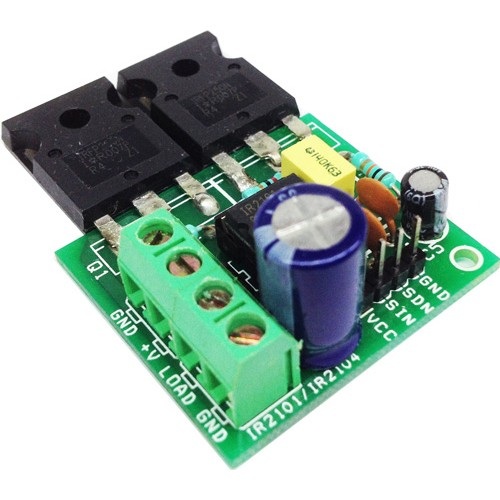
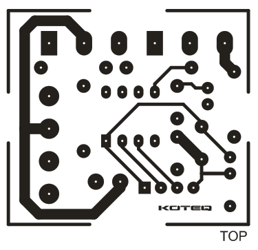
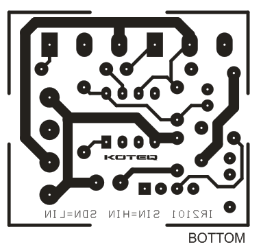
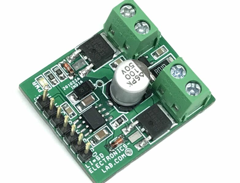
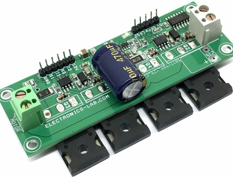
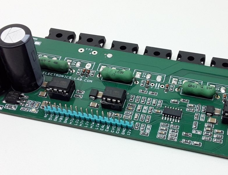
This is a discrete Half-bridge driver based on IR2104 gate driver IC and low impedance high current N channel IRFP4368 MOSFETS. The IR2104 is a high voltage, high speed power MOSFET driver with independent high and low side referenced output channels. HVIC and latch immune CMOS technologies enable ruggedized monolithic construction. The logic input is compatible with standard CMOS or LSTTL output, down to 3.3V logic. A gate IR2104 driver is a power amplifier that accepts a low-power input from a controller IC and produces a high-current drive input for the gate of a high-power transistor such as a power MOSFET. In essence, a gate driver consists of a level shifter in combination with an amplifier.
This drive has many applications, ranging from DC-DC power supply for high power density and efficiency. This project simplifies the design of control systems for a wide range of motor applications such as home appliances, industrial drives, DC brushed motors , Brushless motors, fans, Tesla Coil driver, Induction coil driver, LED driver, Halogen Lamp driver.
Features
- Load Supply 12 to 60V DC
- Load Current 30Amps (Peak 50Amps)
- Logic Supply 12 To 15V DC
- Input Signals 3V to 15V
- IR2104 Single PWM input or IR2101 Dual Input
- Compact Design
- Required Single PWM input and Shutdown
- Screw Terminals for Load and Load Supply
- Header Connector for Logic supply and inputs
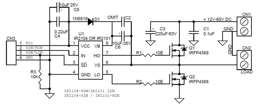
Schematic




Very usefull works great, Thanks a lot
Thanks for your feedback. Have a nice day.
Why is there no coil in this schematic ?
What coil do you mean?
how contact to you
Please use the “Contact Us” form from the link on top menu.
hey can i use this board as a wireless power transmitter at 100kHZ?
Thanks for the good work. I need help on how I can implement that circuit for induction cooker project. How do I connect a microcontroller like arduino so that I can have different power levels in the induction coil
You will need to program Arduino to produce a PWM control signal that will be feed to IN of IC and a shutdown signal to SD. There is a signal graph on the datasheet of IR2104 that will help you a lot.
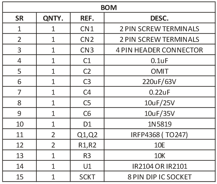
res 1 & 2 10e?
R1 = R2 = 10 Ohm
hello
did this work for you
Discrete means individual components. To say you have a “discrete half bridge driver” means you built this from discrete components, transistors, diodes, resistors, etc… You do not have a discrete driver, you have a gate driver IC. BIG BIG difference, if you don’t believe me go and design build and test a true discrete half bridge driver. Good luck
What was the specific reason for using the IRFP4368 mosfet? You have quite a large bootstrap capacitor, 10uF? It’s probably necessary, but why? To avoid Vgs going above 20V? Is this something you have seen during testing? Sorry about all these questions, but I have a circuit much like this that keeps blowing my IRFZ44n mosfets – I only use 1uF bootstrap capacitor.
Doesn’t discrete mean individual components? The ir2104 is an Ic and not a discrete component.
Does anyone have or know of an actual fully discrete half bridge driver circuit with adjustable deadtime?