Development board for Brushless Motor, DC Brushed Motor, AC Motors (Pre-Driver)
- Rajkumar Sharma
- 900 Views
- medium
- Tested
- SKU: EL111995
- Quote Now
- 0 Likes

The project described here is a pre-driver for brushless motors with a hall sensor. The board incorporates many features like current monitor, fault, speed control, direction control motor start/stop using tactile switches, various function LEDs, 6 PWM LEDs. By combining it with a hybrid IC or IPM module large size high voltage and high current motor can be driven. The project is compatible with the Microchip PICDEM MCLV motor development board, HEX firmware of the MCLV board can directly work with this board. This board is mainly targeted to control brushless DC (BLDC) motors in hall sensor operations. The board supports a free, ready-to-use MC-GUI (Motor Control – Graphical User Interface) from Microchip. Using the MC-GUI, the user can easily set and/or change motor parameters. This greatly helps the user in developing customized drive solutions. Temperature sensor chip U3 is optional so do not populate. The fault pin has to be high for normal operation, bring it to GND to disable the operations. This pin can be used as over current input from ITRIP pin or an over-current comparator of the IPM module. Overcurrent can be monitored using the IMO (RA0) pin of IC in the range 0 to 3V. PWM Frequency default 20Khz with example HEX code. Hex code is available as a download.
This flexible and low-cost board can be configured in different ways to use with Microchip’s specialized motor control microcontrollers. This low-cost board has the facility to use either the PIC18F2331/2431, this hardware can be used to drive AC motor, Brush DC motor, Brushless DC motor, and solenoid. Various inputs and outputs pins are available, microcontroller has dedicated 8 power module PWM, Motion feedback Optical encoder or hall sensors, ADC to connect with a potentiometer, current feed, voltage feedback, and FOC signals. Project is compatible with microchip PICDEM MCLV board, HEX firmware of MCLV board directly can work with this board. This board is mainly targeted to control brushless DC (BLDC) motors in hall sensor operations.
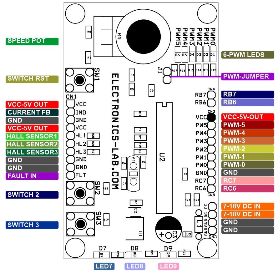
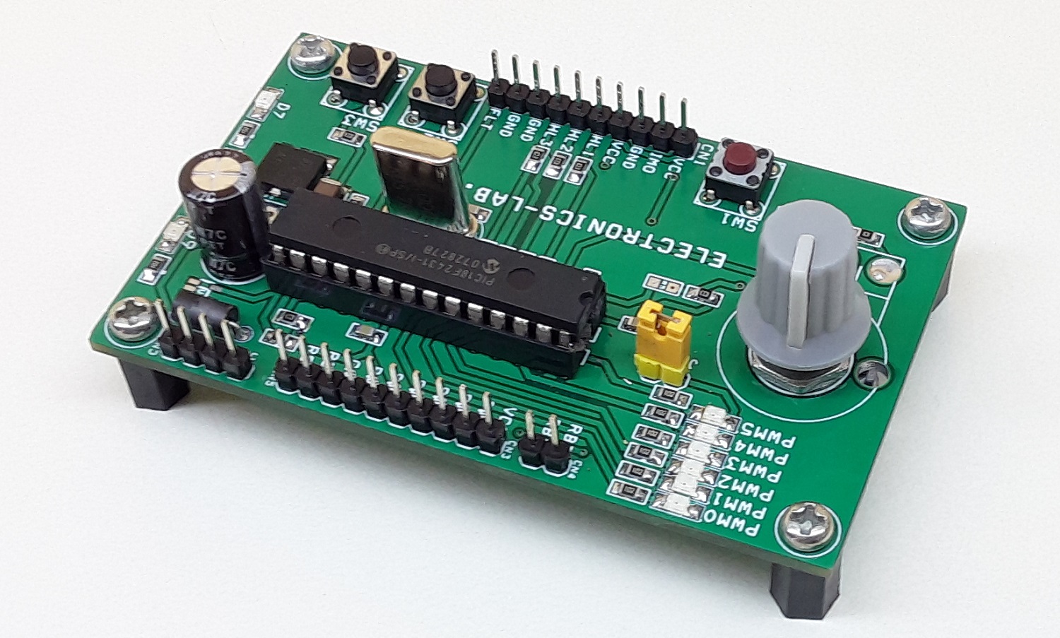
Board Connectors
Connector CN1 (Inputs and Outputs)
- Pin1>>VCC-5V DC Output,
- Pin2>> IMO-Current feedback
- Pin3>>GND
- Pin4>>VCC-5V DC Out
- Pin5>> Hall Sensor 1 (Input)
- Pin6>> Hall Sensor 2 (Input)
- Pin7>> Hall Sensor 3 (Input)
- Pin8>> GND
- Pin9>>GND
- Pin10>>Fault Input (From IPM Trip)
Connector CN2 (DC Supply Input)
- Pin1 >> 7-18V DC
- Pin1>> 7-18V DC
- Pin3>> GND
- Pin4>> GND
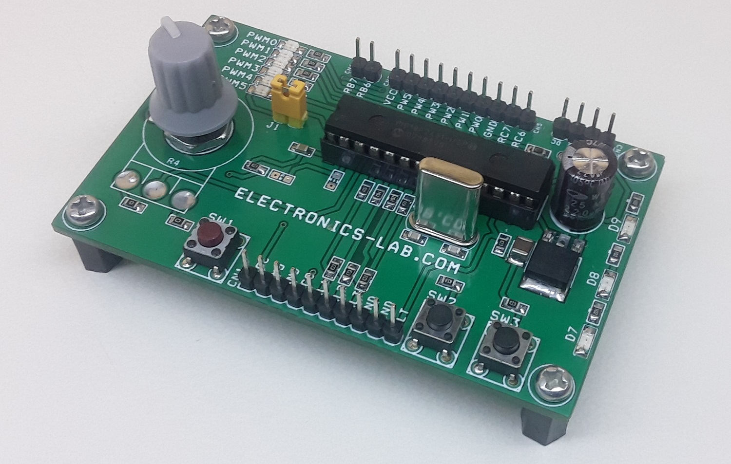
Connector CN3 (PWM Outputs for Hybrid IC, IPM Module)
- Pin1>> VCC
- Pin2>> PWM5
- Pin3>> PWM4
- Pin4>> PWM3
- Pin5>> PWM2
- Pin6>> PWM1
- Pin7>> PWM0
- Pin8>> GND
Connector CN4
- PIN1 >> RB7
- Pin2>> RB6
Connector CN5
- Pin1>>RC7 >> RX RS232
- Pin2>>RC6>> TX RS232
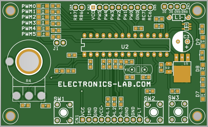
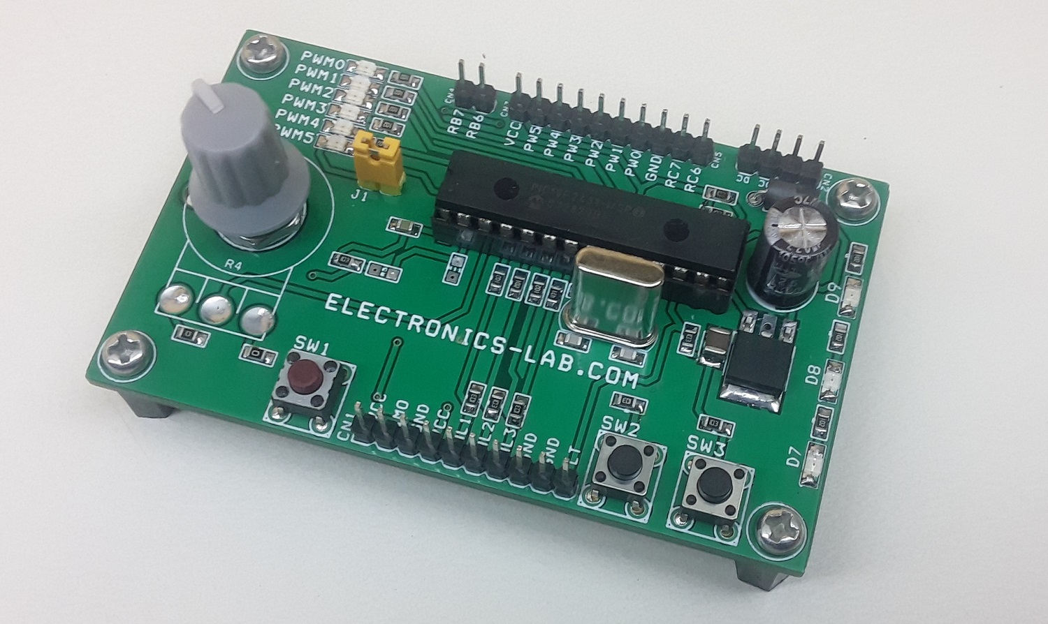
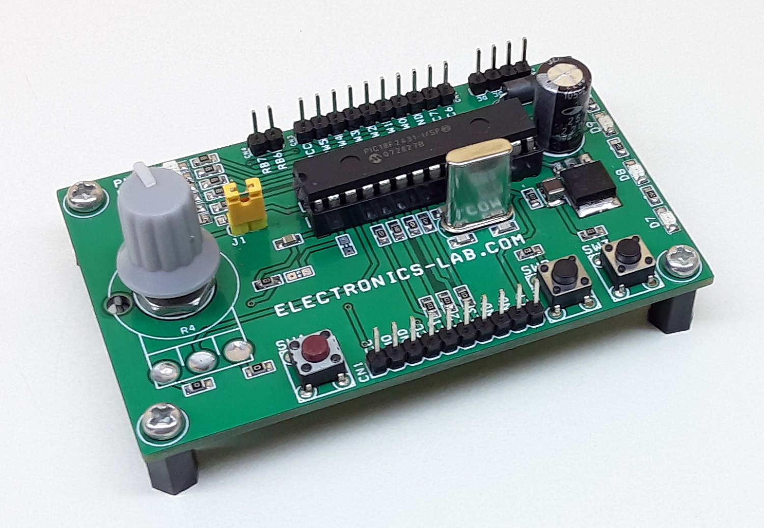
Other Components
- SW1>>Reset Switch
- SW2>>Run/Stop
- SW3>>Direction Change
- Potentiometer R4 >> Speed Control
- Jumper J1 >> Disables PWM LEDs
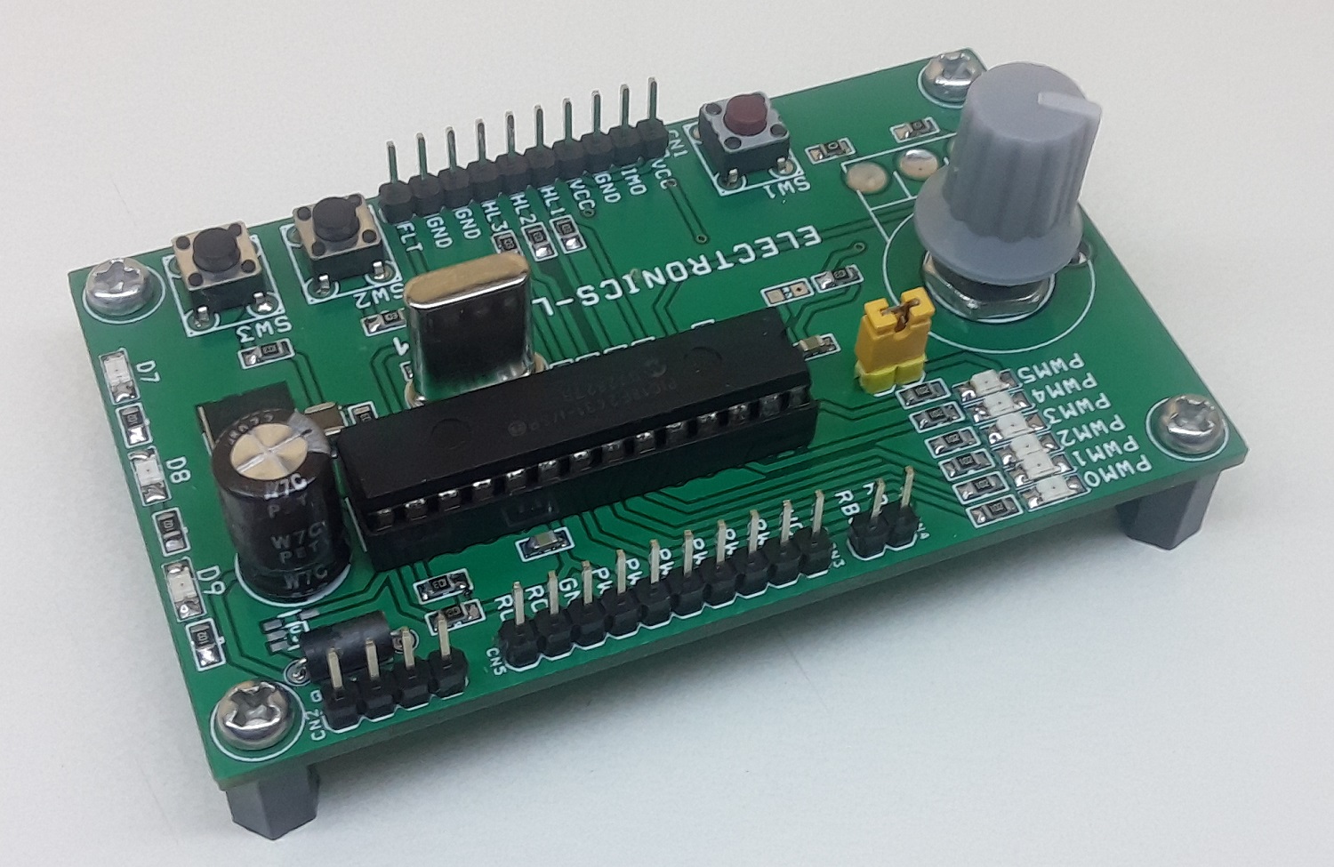
LED
- 6 PWM LEDs =D1, D2, D3, D4, D5, D6
- D7>> Switch Function S2 and S3
- D8>> Switch Function S2 and S3
- D9>> Over Current Fault – If this LED blinks
Operations
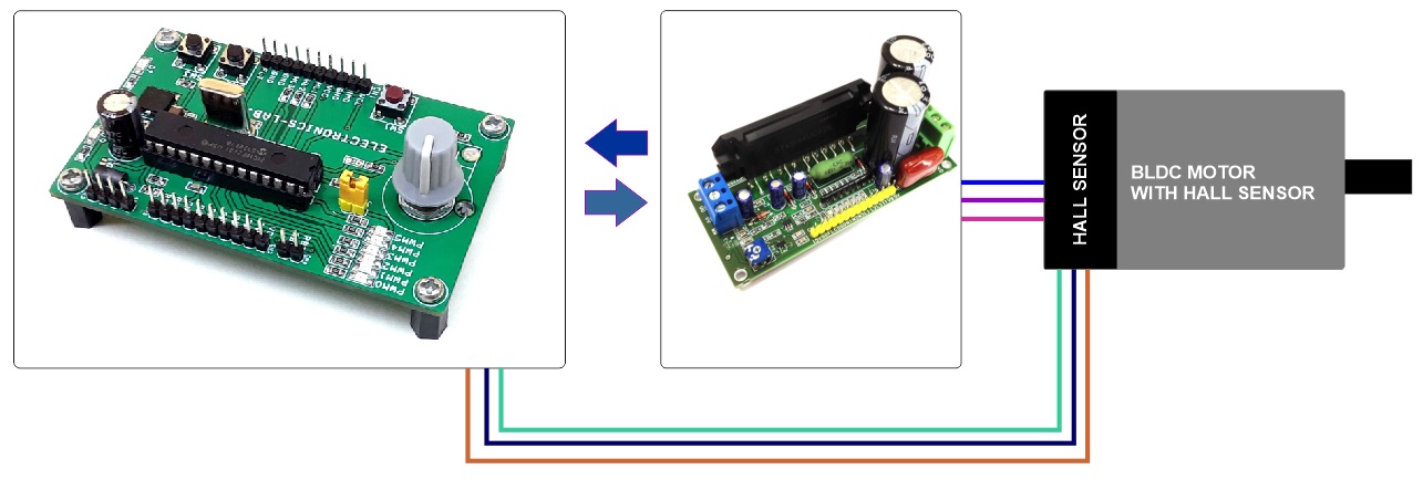
- Connect the board with IPM, Hybrid IC Board 6PWM, ITRIP and Current Sense
- Keep the potentiometer “REF” turned counter clockwise.
- Connect the Power Supply 7 to 18V
- Press and release switch S2 once.
- Turn the potentiometer “REF” clockwise, the motor should rotate.
- Each press of S2 toggles the control between Run and Stop conditions.
- To change the direction of rotation, press S3.
- If the motor stops and LED D1 blinks, it indicates that there was an overcurrent
- Reduce the speed “REF” and press either S2 or S3 to clear the Fault and resume operation
Specifications
- PCB Dimensions: 82.55 x 49.85 mm
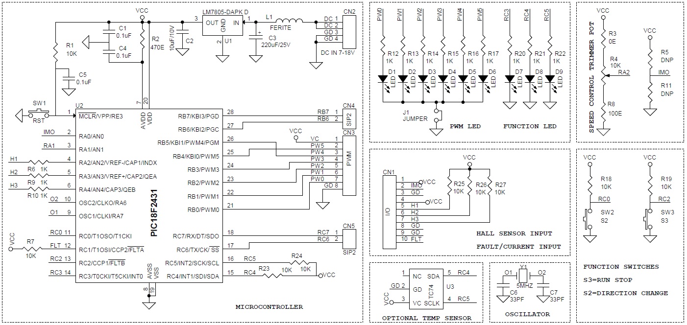
Schematic
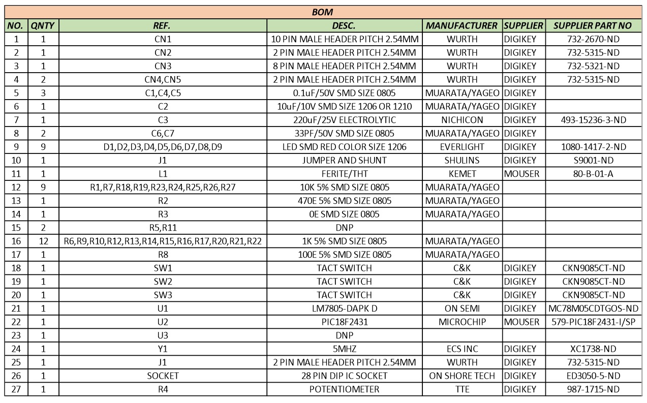
Parts List
Connections
Block Diagram
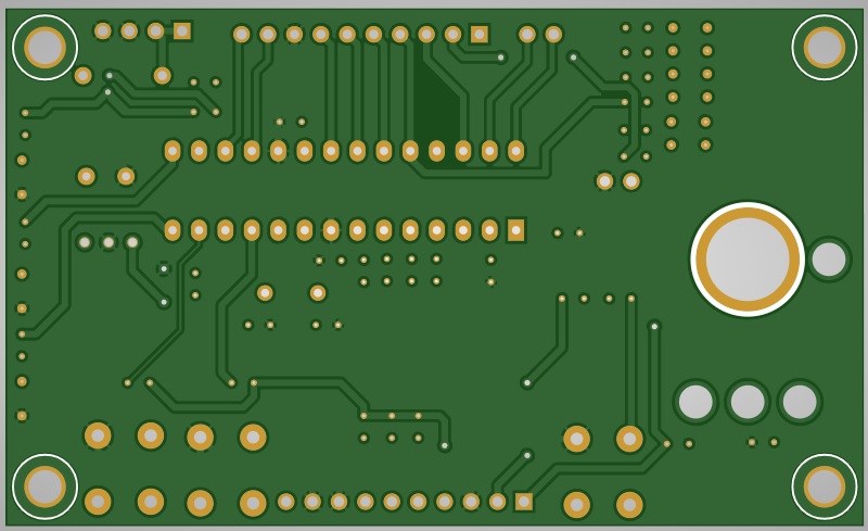
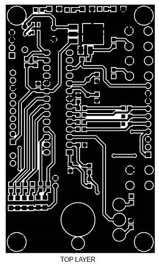
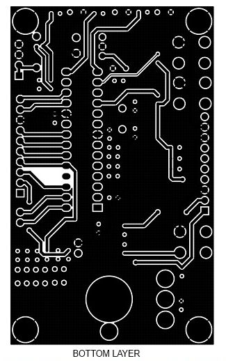
Gerber View
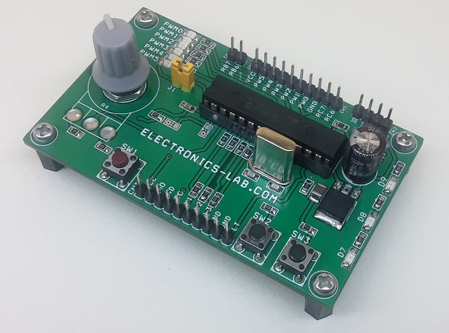
Photos
Video
PIC18F2431 Datasheet
PCB