Infrared Toggle Switch for Home Appliances
- Rajendra Bhatt
- rajbex@yahoo.com
- 29.933 Views
- moderate
- Tested
Introduction
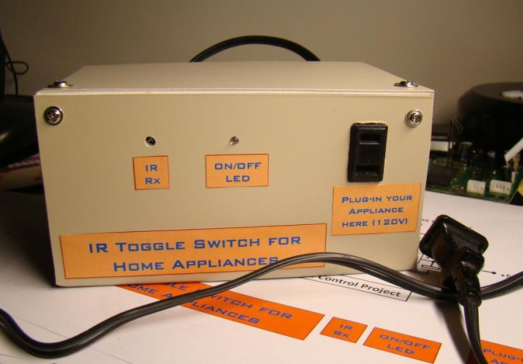
The infra-red (IR) toggle switch project described here is aimed to provide control mechanism for electrical appliances that do not have remote operation features. The goal is to construct a black box where you can plug-in your 120V AC appliance and control ON and OFF operations with any modern IR remote control devices.
Modern IR remote controls generate modulated pulse train of 38KHz frequency when any key on the remote is pressed. With the use of capacitive filtering we will convert the stream of pulses into one pulse regardless of the key entered. This way, we will be able to toggle a relay switch with any key pressed on the remote. This project has been tested with varieties of IR remote control devices like that for TV, DVD, digital camera, etc., and it worked well.
Schematic
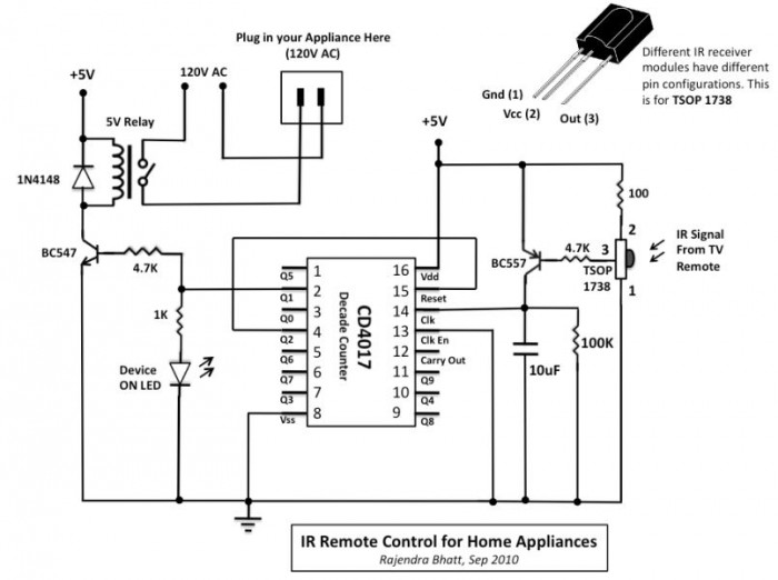
The TSOP 1738 IR receiver module detects the 38KHz input pulses received from the IR remote control device. Under stand-by condition, the output pin of the IR module is at logic High, and when it detects the train of pulses, they appear at its output. The output from IR receiver is fed to a PNP transistor (BC557) with a series base resistor of 4.7K. At the collector of the NPN transistor, the train of pulses will be inverted. There is a 10uF capacitor and 100K resistor connected from the collector to ground. The function of capacitor is to convert the train of pulses into a single pulse, and the resistor is to provide the discharge path for the capacitor.
So lets see what happens when a key on the remote is pressed. During standby, the output of IR receiver module is High, so BC557 is cut off. The capacitor is fully discharged, and the collector of BC557 is at ground. When a key is pressed on the remote, the train of pulses arrived at the base of BC557 turns it ON and OFF very fast. When it is ON, the capacitor gets charged through the collector current of BC557, and when it is OFF, the capacitor starts to discharge through 100K resistor. But the train of pulses is so fast (38000 pulses per second) that the capacitor doesn’t get chance to discharge. So, the bottom line is, every time a key is pressed from the IR remote, a positive going clock pulse is generated at the collector of BC557 transistor.
Next comes CD4017, a decade counter. It counts low-to-high going pulses up to 10 that are arrived at its CLK pin (14) and pulls the corresponding output (Q0-Q9) High. When it is just turned on, Q0 goes High, and when it gets a first low-to-high pulse (when a key is pressed from the IR remote) at CLK i/p, Q0 goes Low and Q1 goes High. Q1 output is connected to a LED through a current limiting resistor to indicate the ON/OFF status. The Q1 output is also used to drive a relay switch through a NPN transistor (BC547). I used 5V DC relay that requires about 70mA current from 5V source to turn ON. This current is provided by BC547.
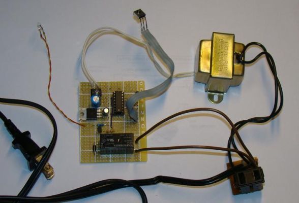
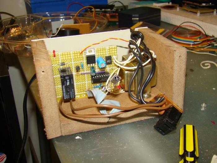
Now, lets see what happens when a key is pressed again. The counter advances by 1, Q1 goes Low (relay is OFF), and Q2 goes High. If we connect Q2 to Reset input of CD4017, the counter is going back to the initial condition (Q0 High, Q1 and all others Low), and is ready to get another key press signal to turn the relay ON. This way the switch is toggled every time a key is pressed from the remote.
Power Supply
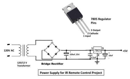
The power supply for the circuit is provided through a 5V regulator IC LM7805. A 12V step-down transformer with a bridge rectifier and a capacitor filter provides an unregulated DC input to LM7805. The regulator IC provides a constant 5V supply for the circuit.
Be careful on the output side of the relay that connects to 120V AC line. A reversed biased diode parallel to the relay input is for back emf protection.
Switch in Operation
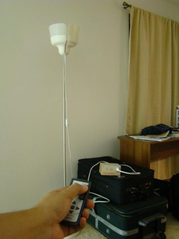
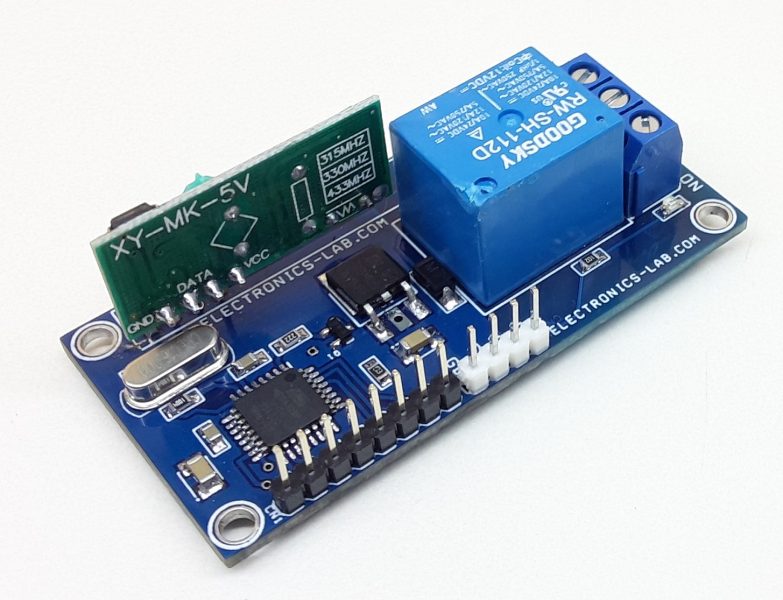
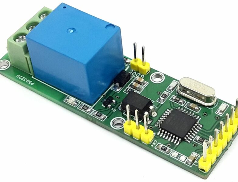
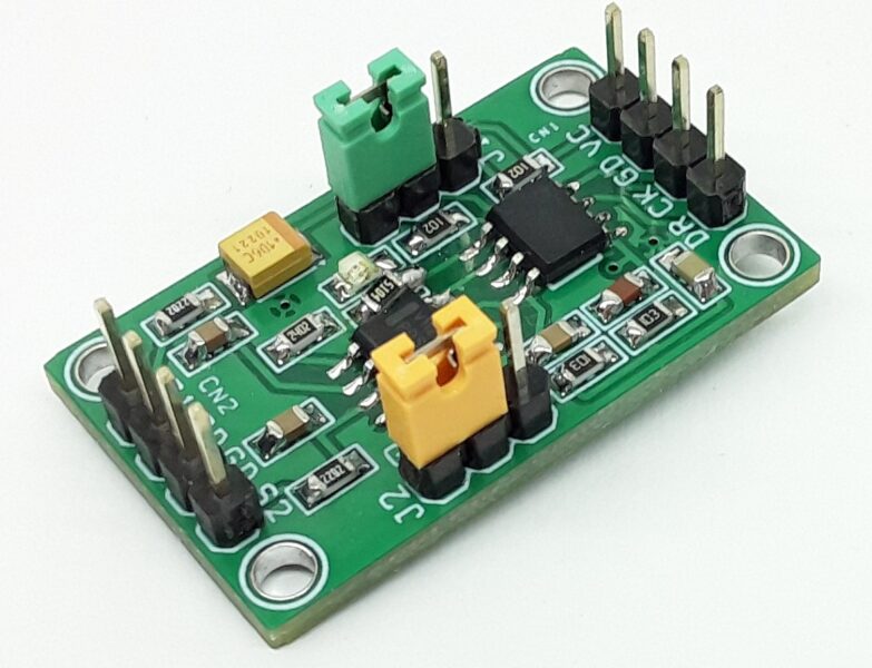
Below are some snapshots showing the IR toggle switch in operation.
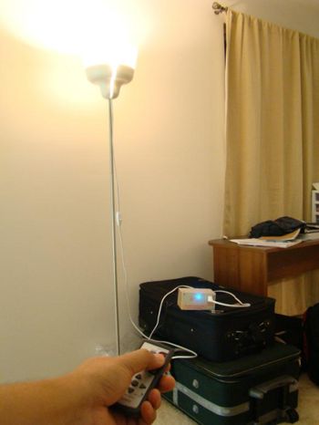


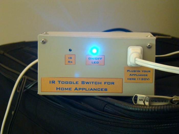


Might not be as useful as expected if this is installed in the same room as where there is a device already controlled via a remote control. Let’s face the fact, this thing will keep on toggling when you’ll change the tv channels, adjust the volume, consult the tv guide, etc…
So it must be used in a room where no other IR control devices are present, therefore what are the odds that there will be a remote control in that room ?
You are right, this circuit is triggered by any button press on an IR remote control, so there must be in a room without any other IR receiving device.
What if you use a remote rd remote that can transmit ir via a separate device port with an ir emitter that would be specific to that device. Place an it “bug/emitter” over the Rx on your device. That would eliminate all the relay chatter?
How can i run 12v relay from this cirkit. If I have to input 12v what changes to do?
TSOP1738 IR receiver has a maximum supply voltage of 6V, so you can’t use 12V power supply on this circuit.
If you have the other components but only have a 12V relay, simply run a wire next to pin 1 of the voltage regulator, the 7805 and label it as +12V. Just next to the relay on the circuit, there is a +5V so in your case that will be +12V. Connect the other end of your wire on that point and you’ll be all set. The relay will work at 12V, because it is connected before the regulator and the TSOP and CD4017 will still have their 5V as initially designed as they still fed by the regulator. Have fun !