3A Thermoelectric Cooler (TEC) Driver
- Rajkumar Sharma
- 81.032 Views
- easy
- Tested
- SKU: EL68625
- Quote Now
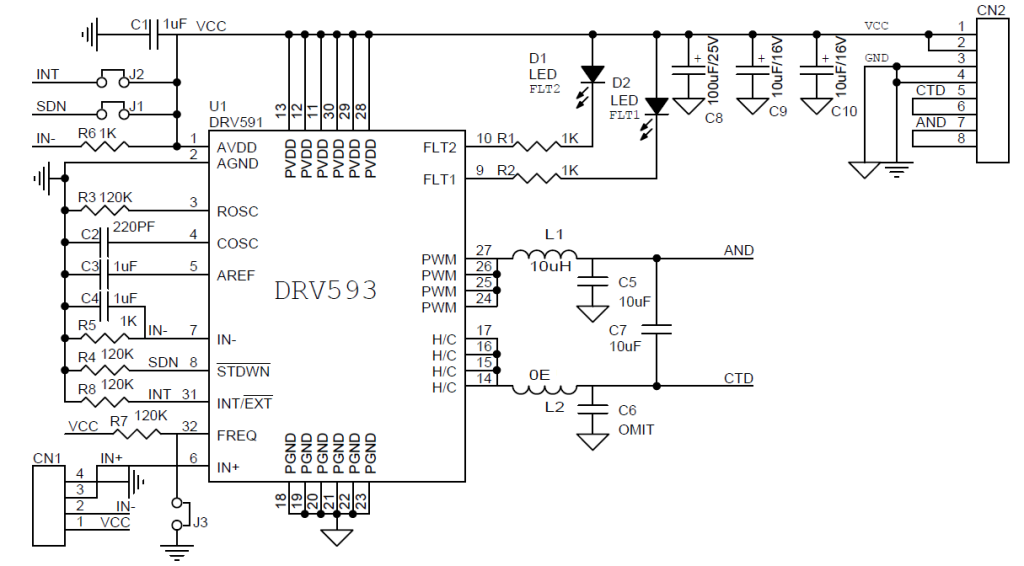
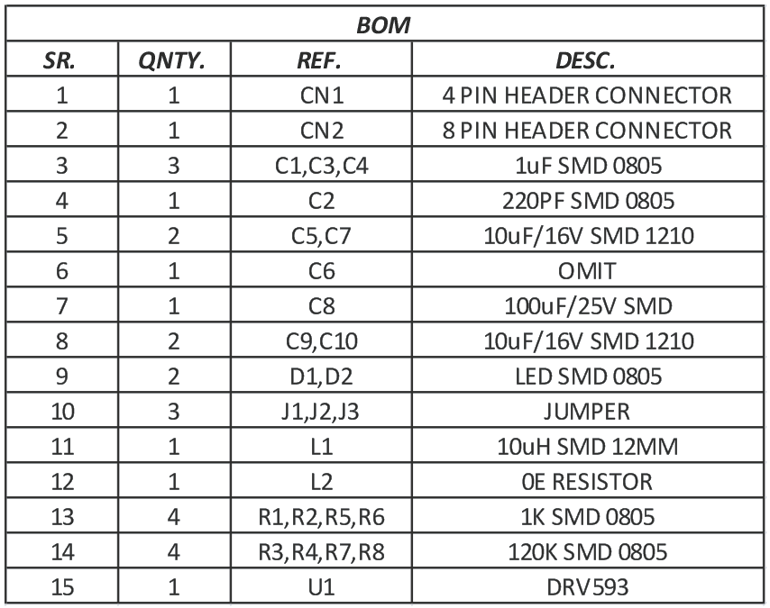
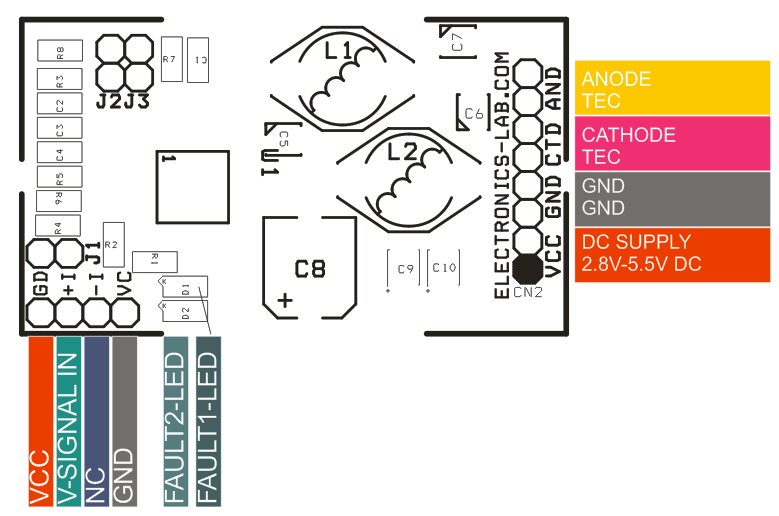
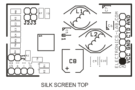
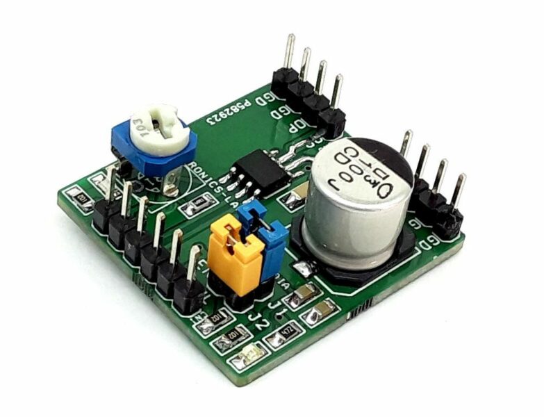
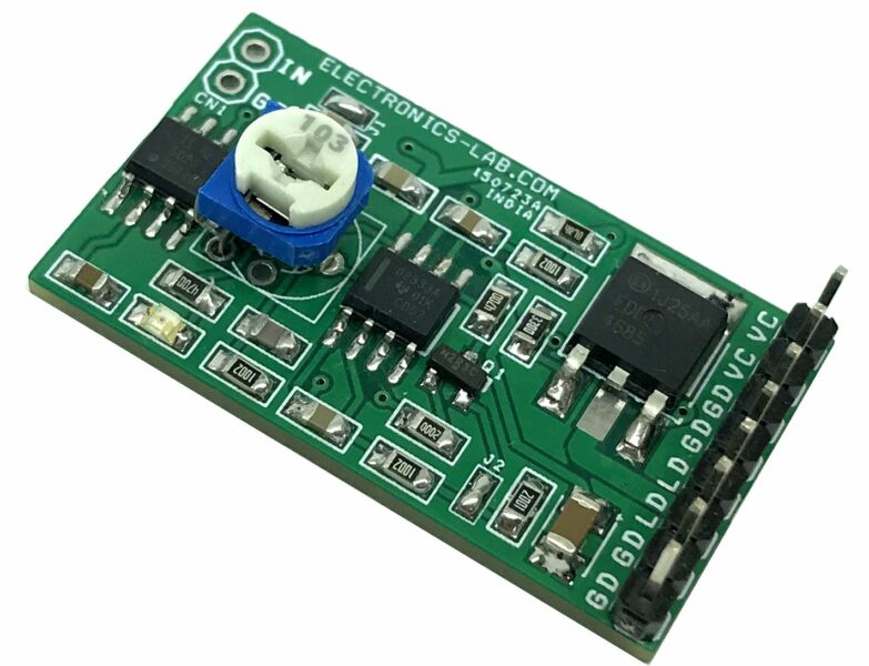
3A TEC Driver Module is a complete power stage solution to drive Thermoelectric Cooler (TEC). The required DC voltage input controls the output current. It consists of the Texas instruments DRV593 power driver IC, along with a few discrete passive components required for operation. It also includes jumpers for configuring the features of the device, LEDs for fault monitoring, and an output filter. The 4 Pin header connector for the inputs, 4-pin header connector for output, and 4 Pin header connector for the power supply provide ease of connection to any system, from an existing design to a bread-boarded prototype. Connect a dc control voltage to CN1 Pin 3 (IN+), ranging from ground to VCC. The Pin 7 of the IC is held to VCC/2 with a resistor voltage divider, as shown in the schematic. Therefore, a dc control voltage of VCC/2 provides 0-V output from PWM to H/C. Input DC voltage range is 1.2V to 3.8V when the supply voltage is 5V and 1.2V to 2.1V when the supply voltage is 3.3V.
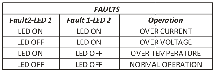
The DRV593 is a high-efficiency, high-current power amplifier ideal for driving various thermoelectric cooler elements in systems powered with 2.8V to 5.5V. The operation of the device requires only one inductor and capacitor for the output filter, saving significant printed-circuit-board area. Pulse width modulation (PWM) operation and low output stage on-resistance significantly decrease power dissipation in the amplifier. The IC is internally protected against thermal and current overloads. Logic level fault indicators signal when the junction temperature has reached approximately 128 degrees centigrade to allow system level shutdown before the amplifier’s internal thermal shutdown circuitry activates. The fault indicators also signal when an over-current circuitry is tripped, and the devices automatically reset. The PWM switching frequency has been set to 500 KHz, this can be changed to 100 KHz by changing capacitor value C2 1nF. The amplifier’s gain is at 2.3V/V.
Features
- 3A Maximum Output Current
- Low Supply Voltage 2.8V To 5.5V
- Frequency 500 KHz (Refer to Note To change Frequency)
- High Efficiency Generates Less Heat
- Over Current and Thermal Protection
- Fault LED for Over Current, Thermal & Under Voltage Conditions
- When J3-Jumper is closed, the board is configured for 500-kHz operation.
Connections
- J2-Jumper closed for normal operation
- J1-Jumper closed for normal operation when the jumper is open device goes into shutdown mode
- The common mode input range is 1.2 V to 3.8 V when using a 5-V supply, and 1.2 V to 2.1 V when using a 3.3-V supply
Schematic





Is it possible to buy this module?
How many pieces do you need? We can produce this if order is >25 pieces.
I need only one. Anyway, thank you for the answer.