USB Low Pin Kit
- Rodrigo Forrequi
- http://rusticengineering.wordpress.com
- lubiana@gmail.com
- 12.075 Views
- moderate
- Non tested
Introduction
USB is very common interface today. If you look around, many of devices today comes with a USB port. Computers, printers, routers, usb keys, etc. All this devices have a USB controller inside. These devices can be divided in two groups:
- USB Host (like a computer, routers, modern LCD TV’s);
- USB Device (like flash drive, mouse, keyboard);
Most of hobby electronic projects still are in RS232 serial communications world. Think in that great market,
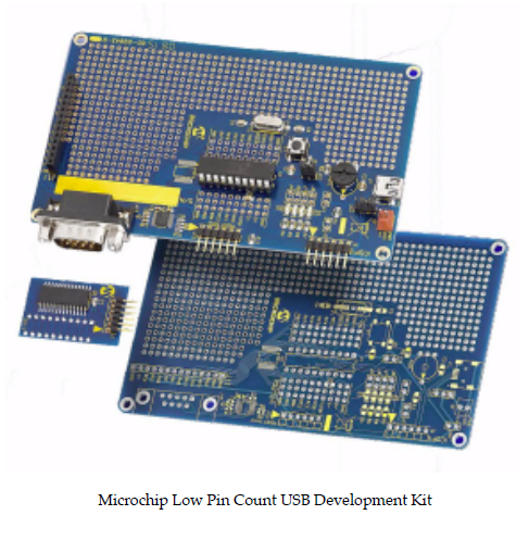
Microchip create a very smart line of microcontrollers, USB capable, to move your projects to future. They have great introductory kits, one of them is the “Low Pin Count USB Development Kit”.
These boards contain a PIC18F14K50 microcontroller and can help you to grow up your USB knowledge and with a few steps you still able to create a mouse device, a USB temperature meter or a USB-Serial converter.
My Project
My idea is create a little board with most of Microchip kit, but less parts then all these boards. Only the basic
components to get the microcontroller up and running the Microchip USB Library examples. PIC18F14K50 is a really
basic device and after some research I found what you can do and what you can not do with it:
- What you can do: USB HID (Human Interface Devices) like mouse, keyboards, sensors, serial-usb converters, etc
- What you can not do: USB storage devices, like USB flash drives
USB storage is a problem because of memory limitations on PIC18F14K50 family.
Design
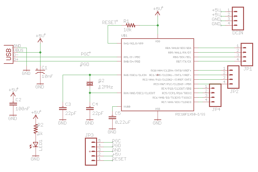
The circuit design is very simples. Basically all you need is
- PIC18F14K50;
- 12MHz Crystal;
- USB connector;
The circuit still have a ICSP header for device programming and debugging. It’s USB powered, so you can pay
attention on current drain (500mA max.). See below:
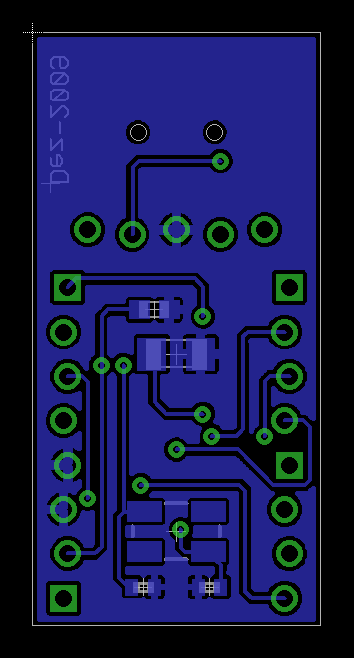
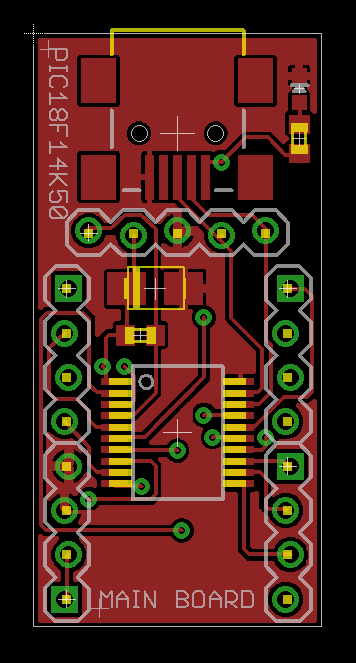
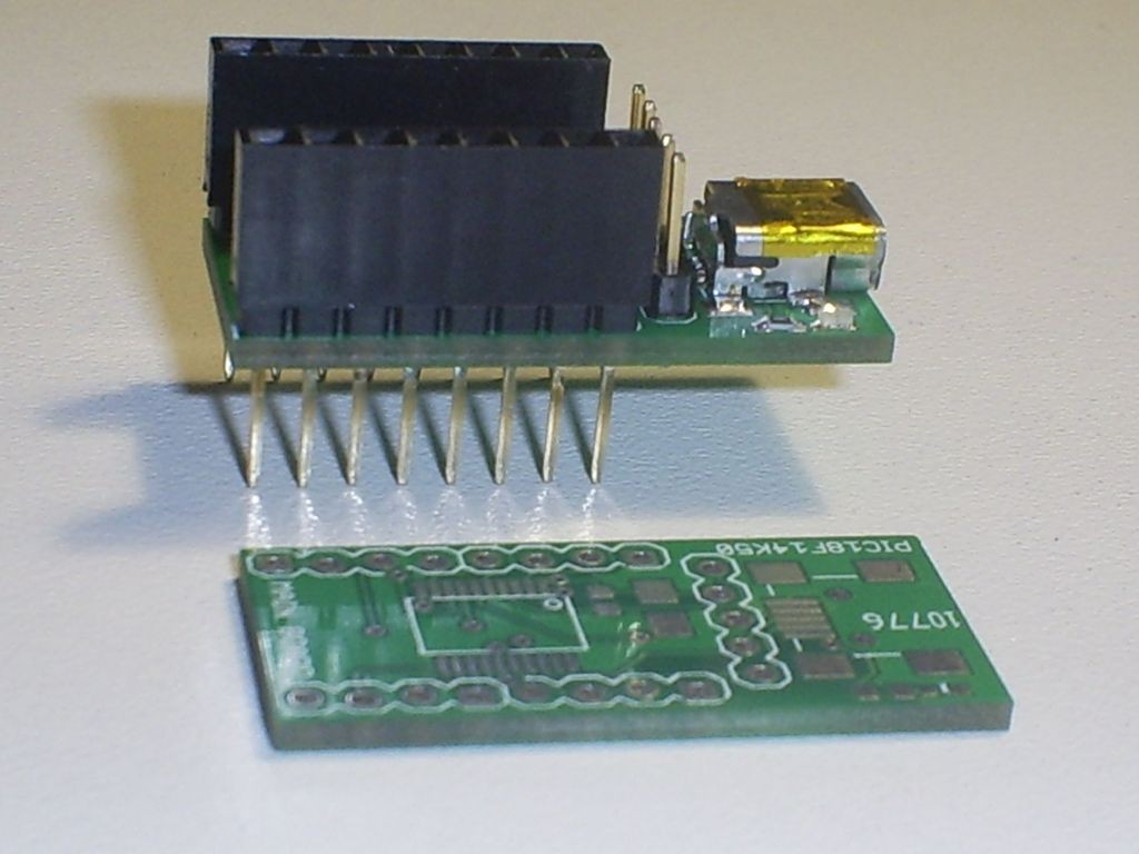
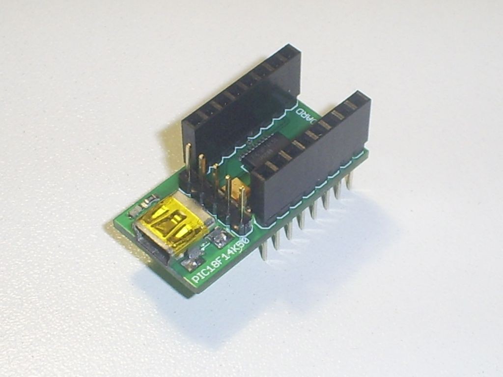
The board is very simple and clean. I want a little device to put on breadboard or stay alone, with headers to
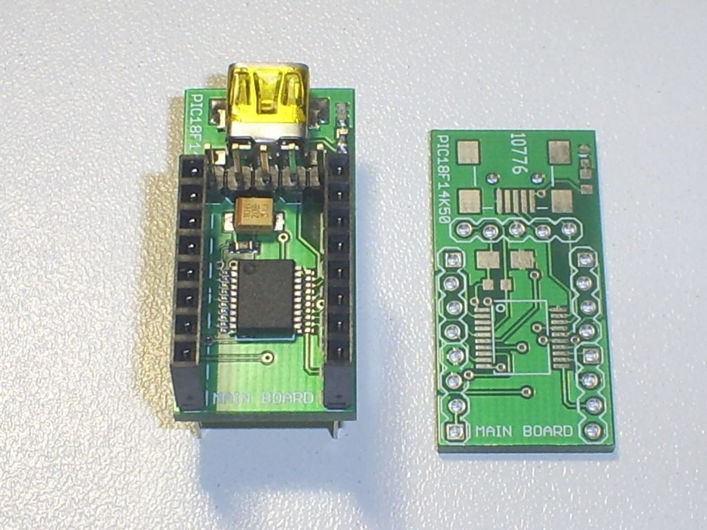
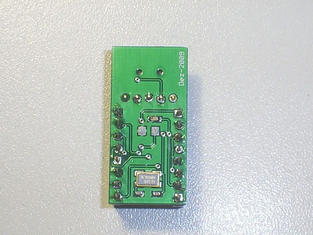
connect wires and breakout boards. I don’t put a RESET switch on board because I think it’s not necessary (does your mouse have a reset button?). The final design you can view above:
Bottom Layer
Top Layer
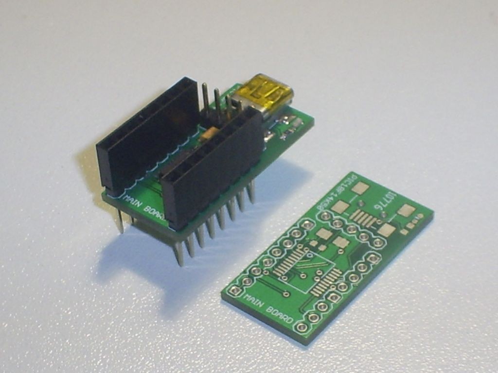
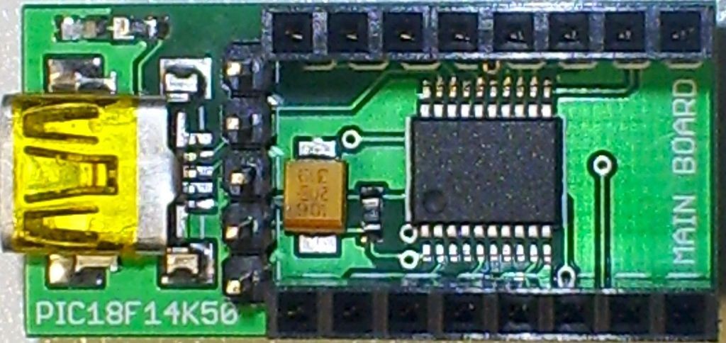
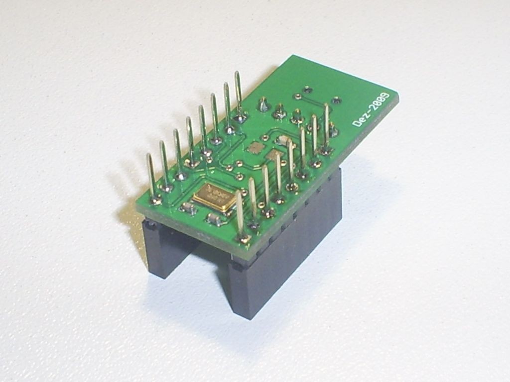
Real board after solder
Conclusion and Tests
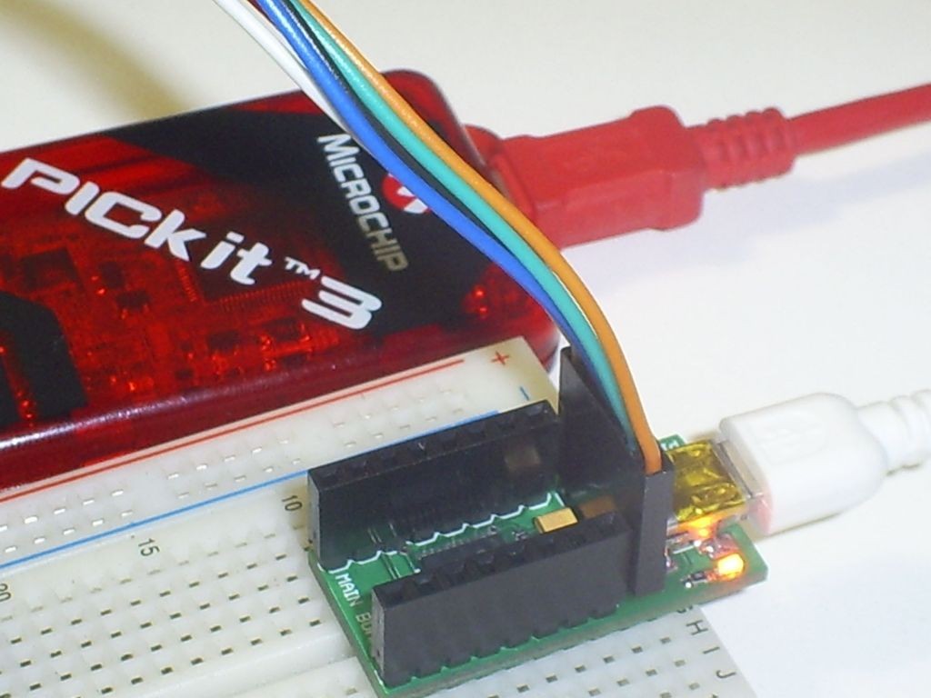
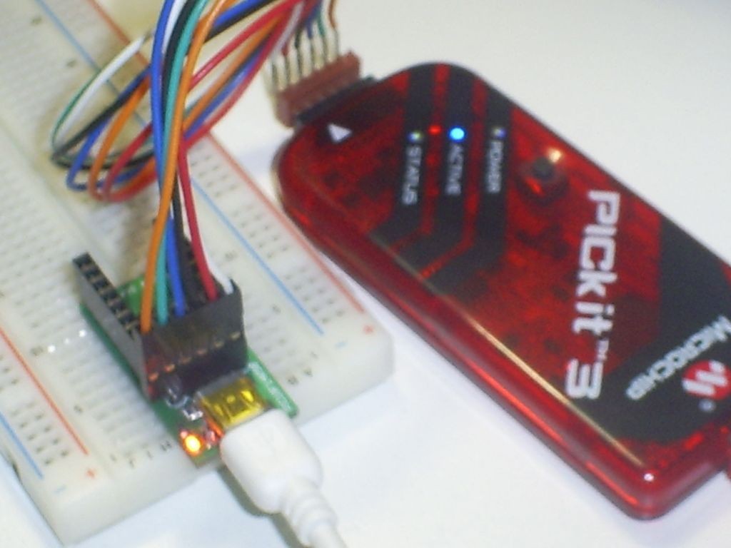
After finish the project I make some tests. The board is very functional and easy to use. To program it I use my PicKit3 program, directly in ICSP connector:
Programming via PicKit3
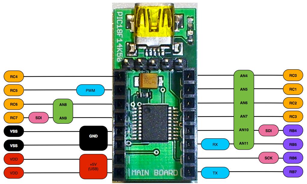
Because the board space, there’s no labels on MCU pins, so I draw a little card to help my mind:
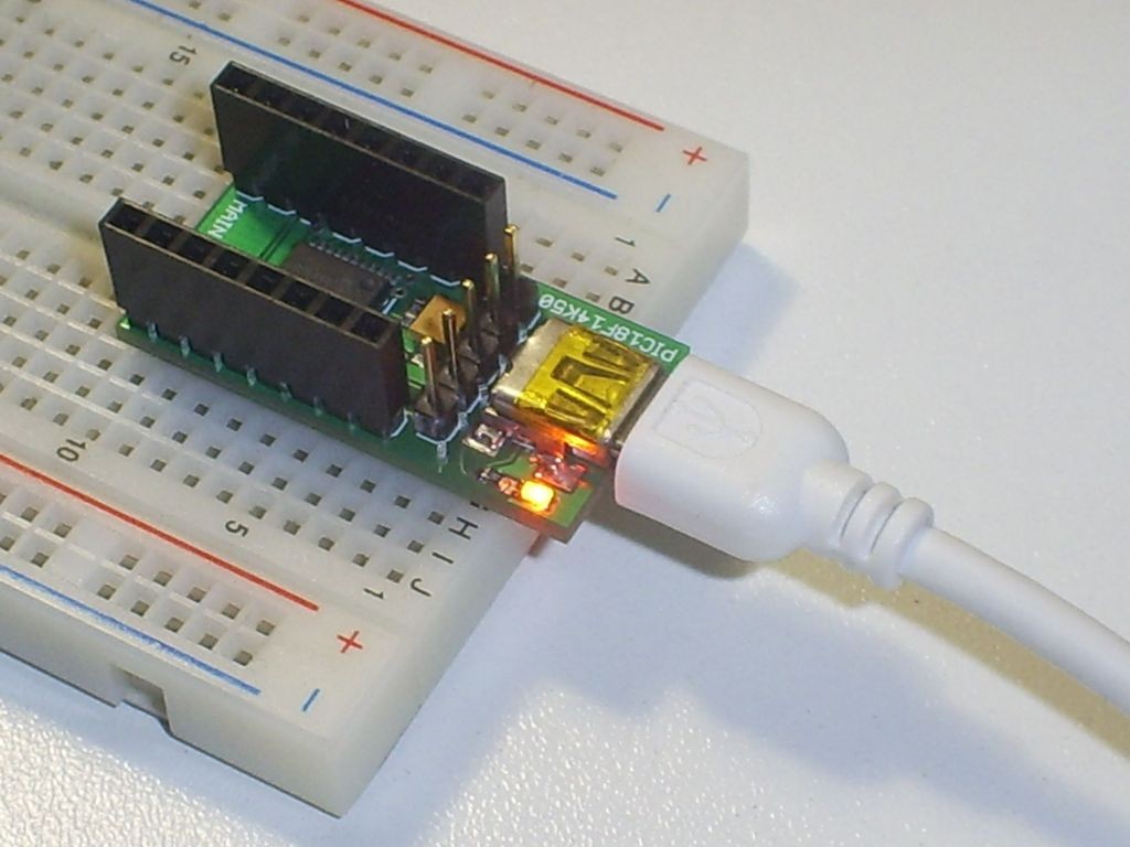
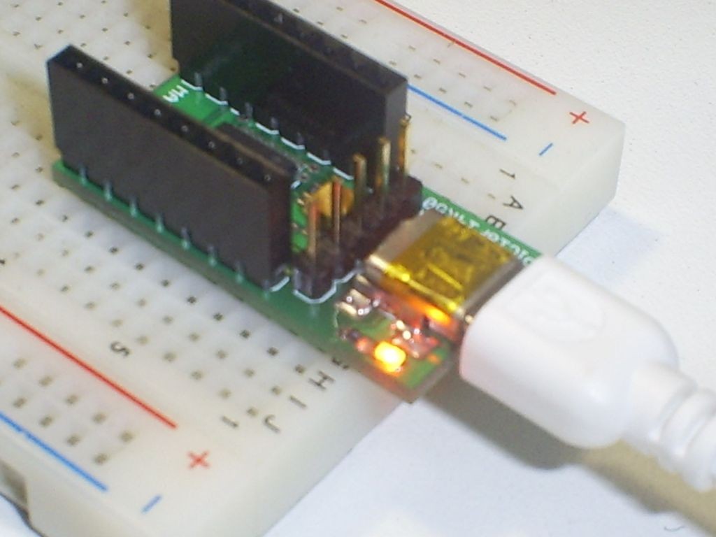
I’ve used long terminal header, to plug it in breadboard. See the next pictures:
After some tests I’m very happy, because:
- All Microchip original kit projects work with my board;
- My knowledge on USB grow up;
- The board is very small, so designs like a mouse with accelerometers is easy to implement;
Rodrigo


