24×6 LED Matrix Control Circuit
- Santi Rodríguez
- santiagoelcabee@hotmail.com
- 44.805 Views
- medium
- Non tested
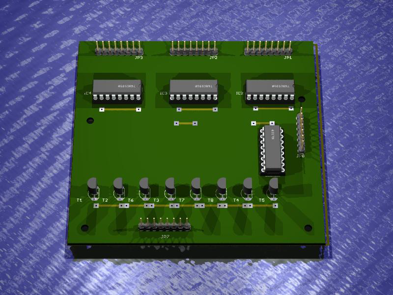
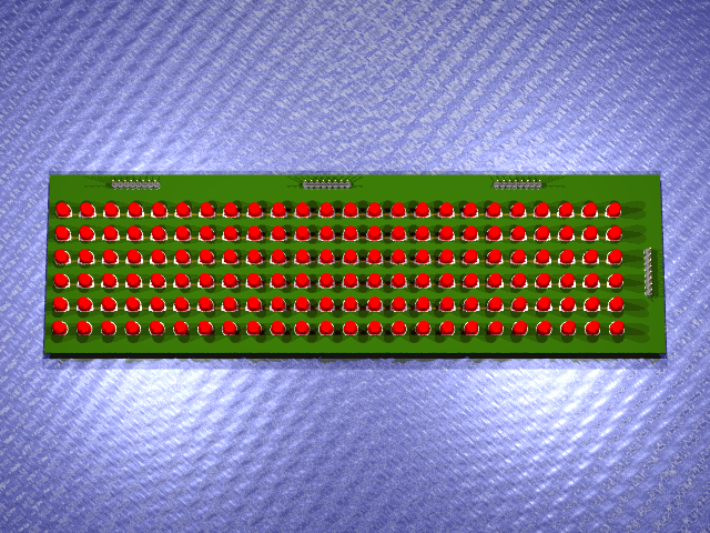
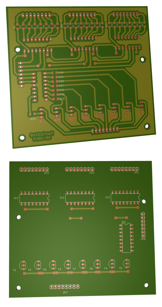
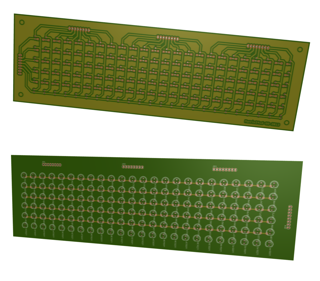
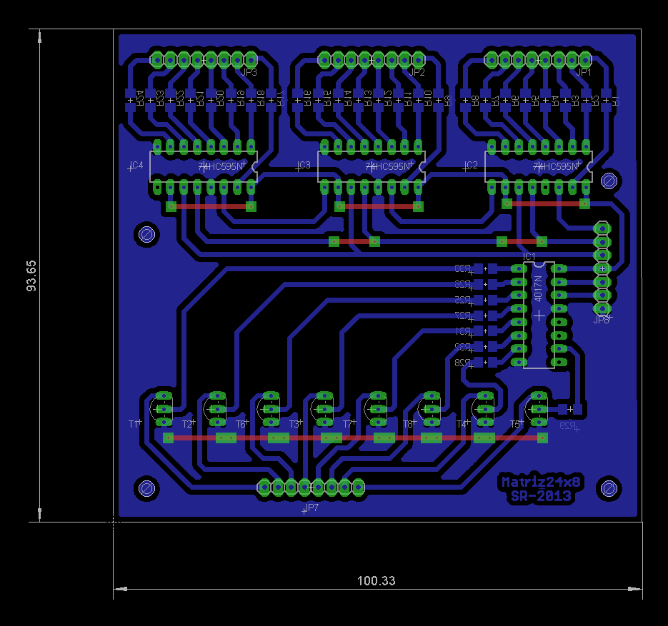
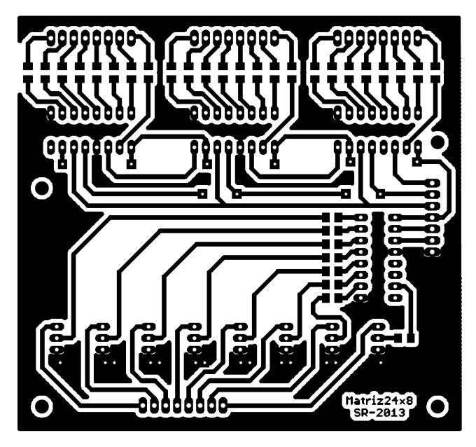
This is a 24×6 LED matrix control board based on Syst3mX schematics on Instructables. The board is connected on the LED matrix board and an external MCU or Arduino is required to produce the control signals that are feed on GP8.
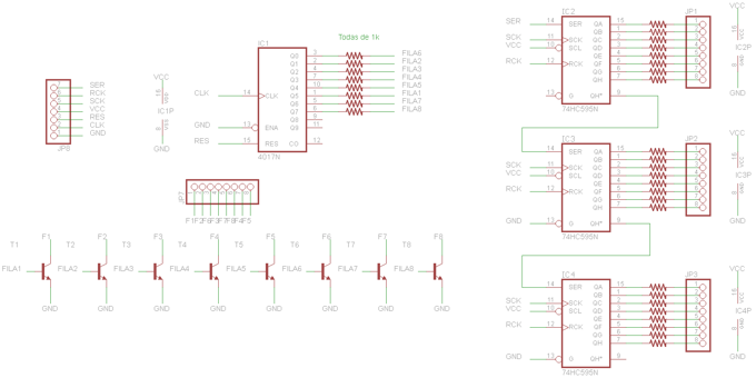
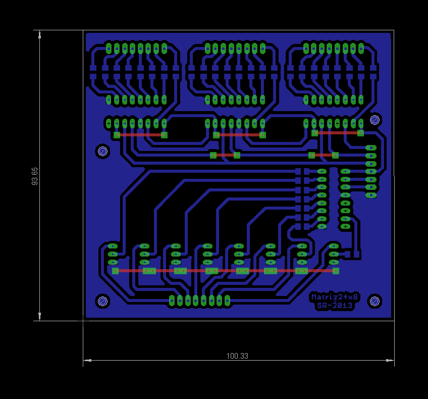
Control Board Schematic
Description
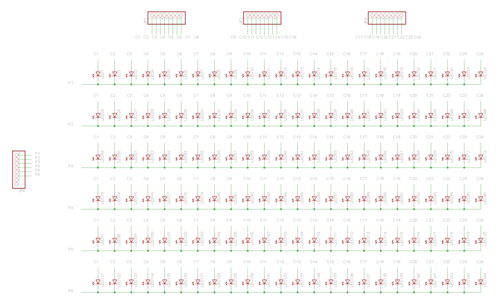
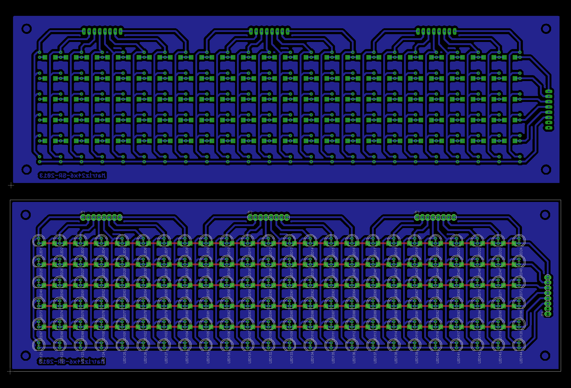
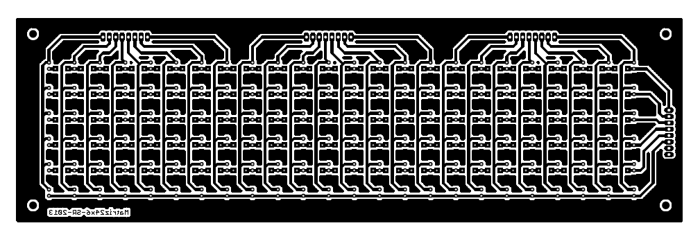
The circuit is able to drive a 24×6 LED matrix using an external MCU or Arduino board. The LED matrix columns are connected on JP1, JP2, JP3 and the 6 rows are connected on JP7. There is also the option to connect 2 more rows (total 8 rows) to make a 24×8 LED matrix.
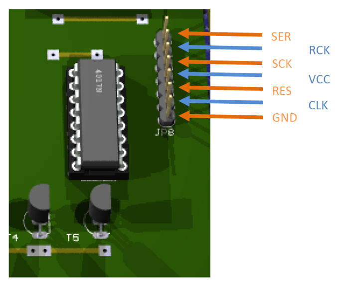
The control is done externally applying the signals on JP8 as is shown on the diagramm below:
- GND is the signal ground
- VCC is 5V in reference to GND
- RCK is SC signal of SPI (latch)
- SCK is CLOCK signal of SPI
- SER is DATA dignal of SPI
- CLK is CLOCK signal of 4017
- RES is RESET signal of 4017
Control signals can be easily generated by an Arduino UNO or Duemilanove using some code . You may refer to:
- http://arduino.cc/en/Reference – general Arduino reference
- http://arduino.cc/en/Reference/SPI – SPI Protocol reference
- Sample Code can be found here
- You can make your own symbols using this EXCEL sheet
- Check how 4017 IC is working: https://www.build-electronic-circuits.com/4000-series-integrated-circuits/ic-4017/
Parts
| R25, R26, R27, R28, R30, R31, R32 | 6 x Resistors of 1k Ohms. SMD, 1206 |
| The rest of resistors in the design | 24 x Resistors of about 100 Ohms. SMD, 1206 |
| IC1 | 1 x 4017 (decade counter) DIP |
| T1, T2, T3, T4, T5, T6, T7, T8 | 8 x 2N3904 |
| IC2, IC3, IC4 | 3 x 74HC595 (shift register) DIP |
| JP1, JP2, JP3, JP6, JP7 | 5 x Pin Header (8×1) |
| 4 x 3 mm screws |





Great design. Do you sell the boards?
We are sorry, we don’t sell board. You may contact the author to ask for the boards.
I want to know about vcc supply for this project and how your code is working.please help me.
The circuit works with 5V supply and please refer to the instructables page for info on the code.
T1, T2, T3, T4, T5, T6, T7, T8 6 x 2N3904
how is it possible or mistake.
It was a typo, it’s fixed now. Thanks for letting me know.
I can not add a column to be 24 more. text above the column 24 will be damaged. sketch must change to produce what I want. ?
You will have to adapt the code if you want to add additional columns, so it will support those columns.
Please tell me size of led control board .
You can try to print it from the PDF files and you will have the actual size. Hope that helps.
I have successfully made a 24 * 9 LED matrix using the above instructions. The text scrolls well when typed from the serial monitor. However I would like when I type a word or numerals or a combination of both-maximum 7- from the serial monitor the text should not scroll but displayed stationary on my matrix.
Kindly attach the code in my email.
please, tell me your pcb size.
Led matrix board size: 267.97 x 83.82mm and control board size: 100.33 x 93.65mm