Using the New ATtiny Processors with Arduino IDE (ATtiny412, ATTiny1614, ATtiny3216, ATtiny1616, ATtiny3217)
- Emmanuel Odunlade
- https://twitter.com/emmaodunlade
- emmaodunlade@gmail.com
- 15.158 Views
- medium
- Tested
While the Arduino series of development boards have ease-of-use features that have made them a darling of the community, there are several situations where using them is not an advisable course of action for a project. Especially in projects where the developers desire a small form factor or the device is required to be low power. As a substitute, developers usually go with Atmeg328p MCU in most situations, but even this increases the size of the project by a significant amount. To solve all of this in recent times, designers turn their attention to a new ATtiny series of microcontrollers and for today’s project, we will focus on how the new series can be used with the Arduino.

They may not be as popular as the Atmega328p microcontrollers, but the new ATtiny series of microprocessors from Microchip such as the ATtiny85 or ATtiny2313 needs no introduction. They power a range of tiny devices like the Digispark series of boards but are unfortunately almost useless in tasking applications as they have very limited Flash (usually less than 8K) and RAM (less than 1K). To improve on this, Microchip has released a new series of ATtiny chips with more memory and functionality, enough to go head-to-head with even some of the more expensive and popular Atmega series of chips.
While these chips had amazing features and capacity, they are plagued with two major downsides:
- They come in SMD packages and are not breadboard compatible, making them difficult to use for DIY hobbyists
- They lack the toolchains possessed by MCUs like the Atmega328p which allows their users to enjoy the same programming ease associated with Arduino boards (and clones).
To go around these downsides, engineers and DIY hobbyists, in no time, started creating different open source solutions that allow the chips to be programmed via the Arduino IDE. For today’s tutorial, we will create an adapter to make the chips breadboard friendly and also examine how someone can use open-source solutions to allow you to program the microcontrollers using the Arduino IDE.
Ready? lets go!
Required Components
The following components are required to build this project:
- ATtiny 16×4 Microcontroller series. (e.g ATtiny1614 )
- Arduino Nano
- 10k Resistor
- 10uf capacitor
- Jumper wires
- Breadboard
These components can be bought from your favorite online stores.
Building the ATtiny Adapter
As mentioned during the introduction, one of the biggest challenges using the new ATtiny series of microcontrollers is their SMD nature which makes prototyping difficult as the chip cannot be plugged directly into a breadboard. To remove this drawback, we will design an adapter for the chip.
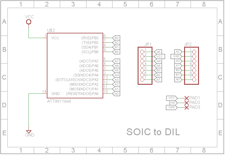
The schematics for the adaptor is a simple one. All we need to do is to route lines from the mounting pads of the ATtiny to header pins. However, this is implemented on a PCB since its the neatest way to implement anything involving SMD components. The adaptor was designed using Eagle CAD and the schematic is shown in the image below;
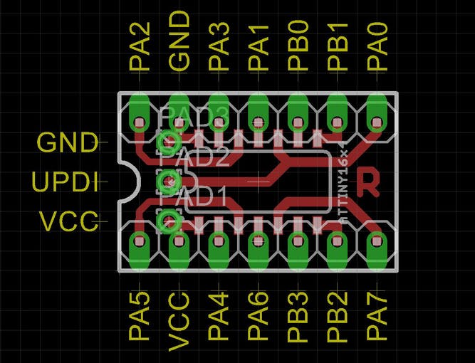
The PCB after the design is shown in the image below:
As you’ve probably noticed, the DIL pin layout of the adaptor is different from the layout of the SMD microcontroller itself. This was done to keep the PCB, single-sided, and to also keep its width within 0.3in, as routing the PCB in such a way that the layout is the same as the SMD chip will require a wider or double-sided PCB. The 0.3in width of the adaptor was intentional, as it is the width required for the adapter to fit into a standard 14pin IC socket.
The breakout pins on the top part of the board, represent the UPDI/RESET, VCC and GND pins through which a programmer can be connected to program the microcontroller. Breaking these pins out at the top of the adaptor board makes it easy to program the ATtiny even when the adapter has been soldered into a project.
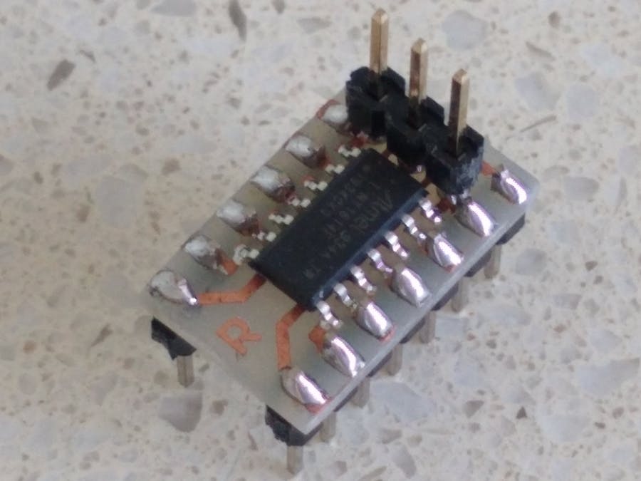
To make it easy for you to print your own PCB, all the Eagle CAD source files, including Gerbers, have been attached to the zip file under the download section. Feel free to either print directly or modify it to suit your needs.
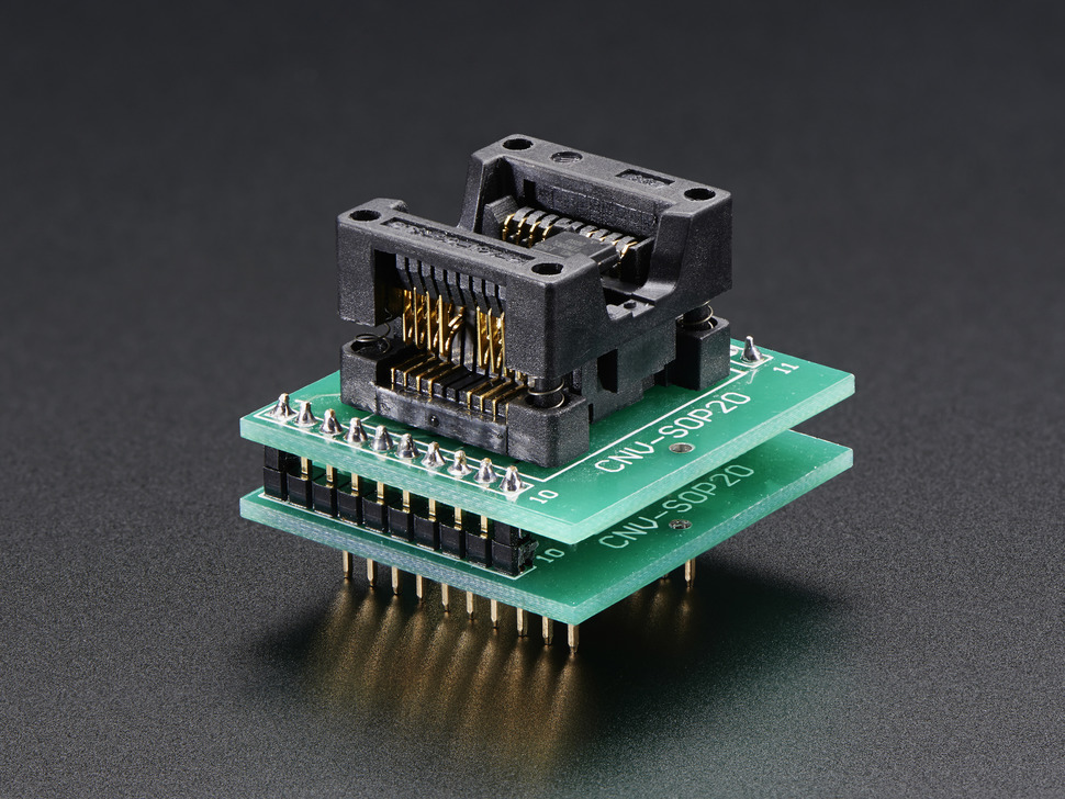
If you will, however, prefer a more flexible adapter that can be reused for multiple chips, without the need to solder and desolder the chips, you can go for this ZiF socket-like adapters on sale at adafruit.
Schematics
With the adapter in place, the next line of action is to connect it to a programmer which will, in turn, be connected to your computer. For today’s project, we will use an Arduino Nano as the programmer and the schematic below shows how the adapter is connected:
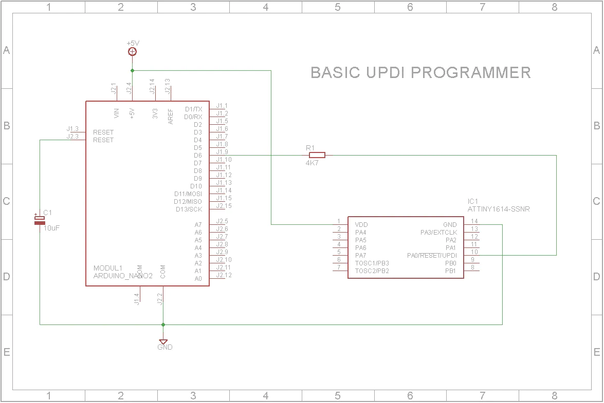
To further highlight the connection, a pin map showing how the components are connected, pin-pin, is provided below:
Arduino – Adapter/ATtiny
GND - GND
5V - VCC
D6 - UPDI
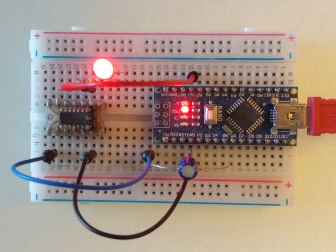
As a demo to show the ATtiny in action, we will implement the Arduino blink example. To do this, connect an LED to the setup as shown below:
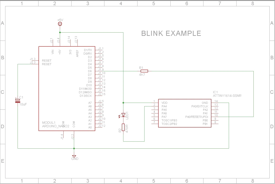
With the programmer and LED connected, we can now proceed to examine the process of uploading code to the ATtiny.
Preparing the Arduino IDE
To bring the ease of programming with the Arduino IDE, which is experienced by the regular Arduino boards and clones, to the new ATtiny MCU series, Spence Conde developed a board package called the megaTinyCore which allows you to effortlessly program the latest series of ATtiny MCUs via the Arduino IDE.
The megaTinyCore requires Arduino IDE version 1.6.3 or later although it was stated on its GitHub page that it may require a much more recent version of the IDE with the initial tests done on version 1.8.9.
The megaTinyCore can be installed on the Arduino IDE in two ways:
- Installation via the Arduino Board Manager
- Manual Installation
I will explore both methods and let you decide which is easiest or faster.
1. Installation via the Arduino Board Manager
The Arduino board manager was designed to make the installation of new boards and add-ons easy for users. To install the megaTinyCore using this method, follow the steps enumerated below:
1. Open the preferences window from the Arduino IDE. Go to File > Preferences or Arduino > Preferences if working from a macOS
2. On the preferences window, locate the “Additional Board Manager URLs” text box and enter http://drazzy.com/package_drazzy.com_index.json into the field as shown below and click the OK button
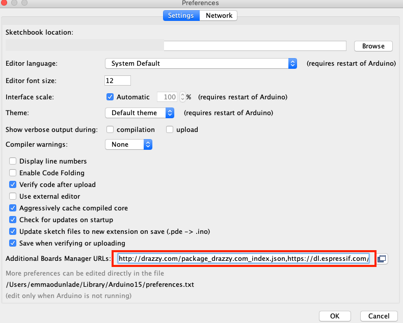
3. Next, open the Arduino board manager. Go to tools>Boards>Boards manager
4. When the board manager opens up, enter megaTinyCore into the search bar and scroll, you will see “megaTinyCore by Spence Konde”, click on install as shown below.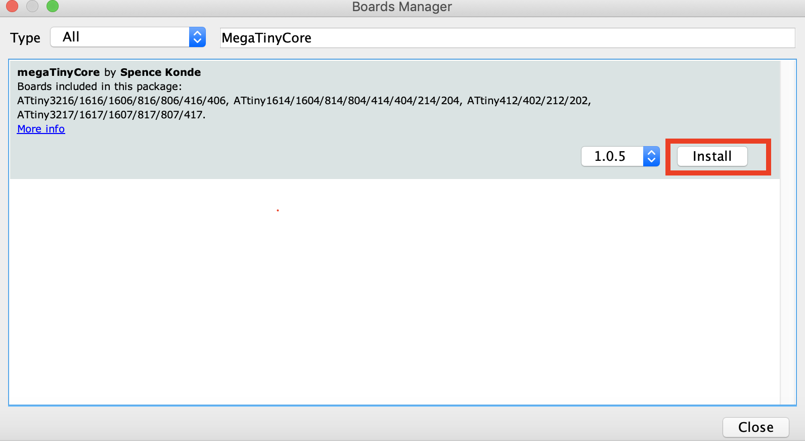
5. Also, search for the “Official Arduino megaAVR boards” package and install the most recent version of that too.
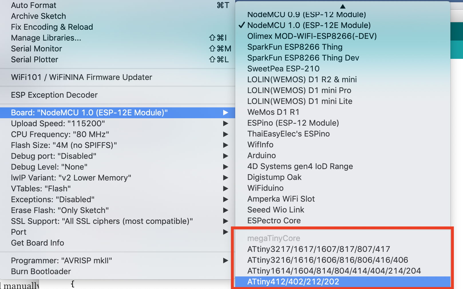
With all of that done successfully, you should now see the Attiny boards all listed under the boards’ section (tools -> Boards) of the Arduino IDE. If that is so, it means the board installation was successful.
2. Manual Installation
The Arduino board manager method provides some level of automation while the manual installation, on the other hand, allows the latest version of the core to be installed, with fixes that may not yet be available in the board manager version of the core. However, to use the manual installation, it is required that you use the board manager to install the latest version of the Official Arduino megaAVR board package for manual installation to work.
Manual installation is recommended if you are interested in contributing to the development of the core, or if having the latest fixes which are not in the released version is important to your build.
To install manually, follow the steps below;
- Ensure you have installed the latest version of the Official Arduino megaAVR board package.
- Download the MegaTinyCore.zip package (either the “released” version or by downloading the .zip of the master repo) on your computer.
- Extract, and place the file in the “hardware” folder inside your sketchbook folder (where your Arduino Sketches are saved). If the hardware folder does not exist, create a new folder and name it “hardware”.
- Restart the Arduino IDE
For automatic updates, instead of downloading the zip file, you can download the GitHub client, and sync this repo to the hardware subfolder of your sketchbook folder.

With the installation steps completed, you should now see the Attiny boards all listed under the boards’ section (tools -> Boards) of the Arduino IDE if the installation was successful.
Transforming the Arduino nano to a UPDI Programmer
Another challenge in the use of the ATtiny chip is the way they are programmed. They use a system called the Unified Program and Debug Interface (UPDI for short). This interface uses the RESET pin to program and/or debug the device. Thus, we need to transform the Arduino nano to a UDPI programmer which will send the correct signals to the UPDI/Reset pin.
To do this, we will use the UPDI Arduino sketch created by ElTangas. The sketch converts ATmega328(p)-based Arduino’s, like the Arduino UNO, Nano, and Pro mini, into a UPDI programmer. The sketch, however, does not work on boards based on other microcontrollers, like the 32u4 (on Arduino Micro/Leo) or non-AVR board.
The following steps show how to do this;
- Close all instances of the Arduino IDE to avoid errors.
- Download and extract the UPDI programmer sketch
- Open the jtag2updi folder after extracting the download
- Open the sketch jtag2updi.ino and upload it to the Arduino board you will like to use, which for our sake is an Arduino Nano. When you open the code, the .ino file will appear empty and that is fine as all the code is contained in the other files in the same folder as the .ino, but the empty .ino is needed so they can be compiled by the IDE.
With the upload successful, you are now ready to use the UPDI programmer. If you use the new ATtiny series a lot, it will be a smart move to totally dedicate an Arduino pro mini or nano board as a permanent UPDI programmer.
Uploading Code to the ATtiny
To show the project in action, We will upload the Arduino blink example to the ATtiny. The Arduino blink example needs no introduction so I won’t bother to go over the code.
With the Arduino Nano connected to the ATtiny as described under the schematics section, open the blink example by going to File->Examples->Basics->Blink.
With the example is opened, select the board type and set the programmer (Tools->programmers (scroll towards the end)) as jtag2updi (megaTinyCore).
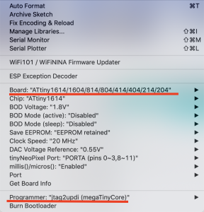
Add the line of code below, before the setup() function to indicate the pin to which the led is connected (since the chip doesn’t have a built-in LED)
#define LED_BUILTIN 0 //PA4 (Pin 2)
An important thing to note at this point is the pin map below which shows how the Physical IOs should be referenced with Arduino C functions like digitalRead, digitalWrite, analogRead, or analogWrite. For instance, PA4 which is labeled as pin 2 on the chip is referenced as 0 within the Arduino IDE.
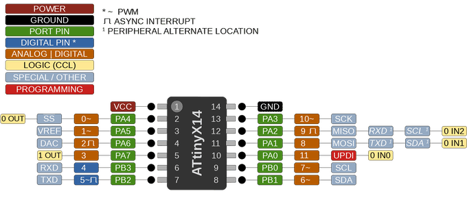
Also note that, unlike the ATmega328 MCU, the new ATtiny processors don’t have separate analog pins. All can be used as either analog or digital, depending on how it is declared within the code.
With the above done, verify the code and hit the upload button. You should in time begin to see the LED blinking. At this point, feel free do disconnect the Arduino nano and power the ATtiny from a 5VDC source.
That’s it!
You can now deploy the new ATtiny series of microcontrollers in your project. Saving space and money. Unlike the former ATtiny microcontrollers, these new series of MCUs come with a higher amount of flash memories, cost a whole lot less, and are all-around more efficient. I advise they should be considered as the MCU of choice for your next tiny, low-cost, low-power project.




If they are like the 85 you can do hid stuff.
The parts list says 10k resistor but the drawing says 4k7. Which is it please?
I just get ‘A programmer is required to upload’ Why would this be please?