Using the 433MHz RF Transmitter and Receiver with Arduino
- Nick Koumaris
- http://educ8s.tv
- info@educ8s.tv
- 84.648 Views
- moderate
- Tested
Introduction
While building microcontroller based projects, there are occasions where communication will be required between two devices, either in a duplex/transceiver based operation (where both devices can transmit and receive at the same time) or in a simplex-based operation where communication is one way (Receiving device cannot transmit and the transmitting device cannot receive).
Several options exist for implementing any of the two communication modes mentioned above and the selection of a particular option, usually depends on the specification of the project, especially the distance between the devices and cost. For short range, low-budget communication between two microcontrollers, one of the most preferred medium used is Radio Frequency (RF) communication using the 433MHz RF transmitter and receiver modules. For today’s tutorial, we will look at how to use these modules to establish communication between two Arduino boards.
The 433 MHz Transmitter and Receiver Modules
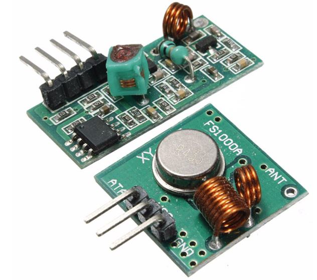
These modules are very popular among makers and DIY enthusiasts due to their low cost and ease of use. They are used in all forms of short-range, simplex-based communication between two microcontrollers with one of the microcontroller serving as the transmitter while the other serves as the receiver. These modules are ASK (Amplitude Shift Keying) or OOK (Of Hook Keying) type RF modules, that means they usually draw no power when transmitting a Logic “zero” and as such consumes a significantly low amount of power. This low power consumption makes them very useful in battery-based implementations.
Some of the specifications of the transmitter and receiver modules are listed below.
Transmitter Specifications

- Working voltage: 3V – 12V
- Working current: max Less than 40mA max, and min 9mA
- Resonance mode: (SAW)
- Modulation mode: ASK
- Working frequency: 433.92MHz
- Transmission power: 25mW
- Frequency error: +150kHz (max)
- Velocity: less than 10Kbps
- Transmission range: 90m (in open space)
Receiver Specifications
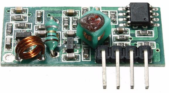
- Working voltage: 5.0VDC +0.5V
- Working current:≤5.5mA max
- Modulation mode: OOK/ASK
- Working frequency: 433.92MHz
- Bandwidth: 2MHz
- Sensitivity: exceeds –100dBm (50Ω)
To demonstrate the ease with which wireless capabilities can be added to projects using these modules, we will build a weather station with remote data display. The weather station will comprise primarily of a temperature and humidity sensor and the 433 RF transmitter module. It will measure the temperature and humidity of the environment and send it via the RF transmitter to the display unit (received via the RF receiver module) on a ST7735 1.8″ Color TFT LCD display.
Required Components
The following components are required to build this project:
- Cheap Arduino Uno
- 433Mhz RF Kit
- DHT22
- 1.8″ Color TFT
- Small Breadboard
- Wires
- Powerbank
- Jumper wires
- Battery holder
As usual, all of these components can be bought via the links attached above.
Schematics
There are two schematics for this project. The first one is for the transmitter which obtains temperature and humidity from the environment and sends it to the second half of the project, the receiver, which displays the data on the display.
Schematic for the Transmitter
The transmitter circuit comprises of an Arduino, the DHT22 temperature and humidity sensor, and the 433 MHz RF transmitter module. A battery pack can be added to provide power to the Arduino when its disconnected from the computer. Connect the components as shown below.
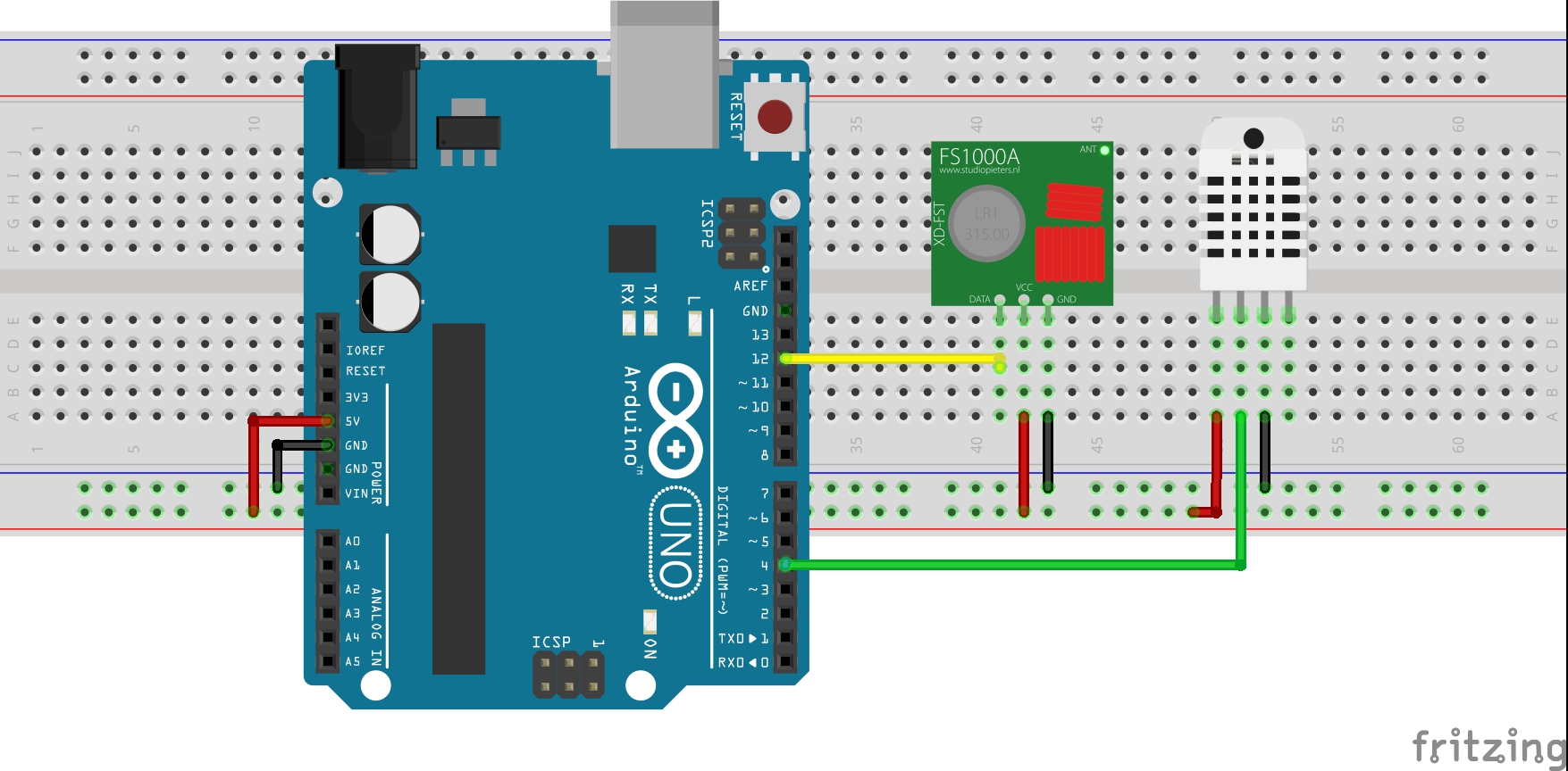
For clarity, the pin connections between the Arduino and the other components are displayed below.
Arduino – 433 MHz Tx Module
5V - VCC
12 - Data
GND - GND
Arduino – DHT22
5V - VCC
D4 - Signal
GND - GND
Schematics for the Receiver Circuit
The receiver is made up of the 433 MHz RF receiver module, the ST7735 1.8″ Color TFT Display, and an Arduino Uno. Connect the components as shown below.
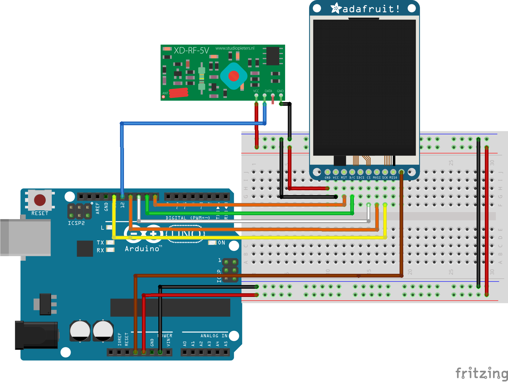
Due to a variation in pinout of the display from one manufacturer to another and for clarity, the pin connection between the Arduino and the other components that make up the receiver are mapped out below:
1.8″ TFT – Arduino
LED - 3.3v
SCK - D13
SDA - D11
DC - D9
Reset - D8
CS - D10
GND - GND
VCC - 5v
Arduino – 433MHz Rx Module
5V - VCC
D12 - DATA
GND - GND
To better understand the use of the ST7735 1.8″ Color display with the Arduino, check out one of our previous tutorial on connecting the display to the Arduino.
With the connections all done, we can now proceed to write the code for this project.
Code
Just like we had to build two devices, we will write two different codes for this project. One of the codes is to control the transmitter and the other to control the receiver.
To easily write the code for this tutorial, we will use the libraries that make it easy to drive each part of the project. For the RF modules, we will use the virtual wire library, to send and receive data, while for the display of the received data, we will use the Adafruit GFX and the Adafruit ST7735 libraries to easily update the ST7735 LCD display. To cap it, we will use the Adafruit DHT sensor library to easily obtain temperature and humidity data from the DHT22 sensor.
The algorithm behind the code is simple. For the transmitter, obtain the temperature and humidity values from the DHT22 and send via the RF transmitter to the receiver. For the receiver, obtain the temperature and humidity value sent by the transmitter using the RF Receiver module and display on the LCD.
As usual, I will do a brief explanation of the code for the two halves of the project starting with that of the transmitter.
Transmitter code
We start by including the libraries that will be used within the code.
//Written by Nick Koumaris
//info@educ8s.tv

#include <VirtualWire.h>
#include "DHT.h"
After this, we declare the pin of the Arduino to which our DHT is connected and also specify the type of DHT being used.
#define DHTPIN 4

#define DHTTYPE DHT22
Next, we indicate the pin of the Arduino which will be used as our data transmission pin (which is connected to the data pin of the RF transmitter module) and create a struct package which will be used for sending the data.
const int led_pin = 13;
const int transmit_pin = 12;

struct package
{
  float temperature ;
  float humidity ;
};
Next, we define the type for the package and create an instance of the DHT class to address the DHT sensor.
typedef struct package Package;
Package data;

DHT dht(DHTPIN, DHTTYPE);
With this done, we move to the void setup() function where we set the TX pin and other parameters to initialize the RF module.
void setup()
{
    // Initialise the IO and ISR
    vw_set_tx_pin(transmit_pin);
    vw_set_ptt_inverted(true); // Required for DR3100
    vw_setup(500);       // Bits per sec
    pinMode(led_pin, OUTPUT);
}
Up next is the void loop() function where we obtain the temperature and humidity using the read sensor function. After obtaining the data, it is sent using the vw_send() function. A 2000ms delay time is implemented to create an interval between the data and ensure one is sent before the other.
void loop()
{
  digitalWrite(led_pin, HIGH); // Flash a light to show transmitting
  readSensor();
  vw_send((uint8_t *)&data, sizeof(data));
  vw_wait_tx(); // Wait until the whole message is gone
  digitalWrite(led_pin, LOW);
  delay(2000);
}
The complete code is written below and attached to the zip file under the download section.
#include <VirtualWire.h>
#include "DHT.h"

#define DHTPIN 4

#define DHTTYPE DHT22

const int led_pin = 13;
const int transmit_pin = 12;

struct package
{
  float temperature ;
  float humidity ;
};


typedef struct package Package;
Package data;

DHT dht(DHTPIN, DHTTYPE);

void setup()
{
    // Initialise the IO and ISR
    vw_set_tx_pin(transmit_pin);
    vw_set_ptt_inverted(true); // Required for DR3100
    vw_setup(500);       // Bits per sec
    pinMode(led_pin, OUTPUT);
}


void loop()
{
  digitalWrite(led_pin, HIGH); // Flash a light to show transmitting
  readSensor();
  vw_send((uint8_t *)&data, sizeof(data));
  vw_wait_tx(); // Wait until the whole message is gone
  digitalWrite(led_pin, LOW);
  delay(2000);
}

void readSensor()
{
 dht.begin();
 delay(1000);
 data.humidity = dht.readHumidity();
 data.temperature = dht.readTemperature();
}
Receiver Code
As usual, we start by including the libraries that will be used.
//Written by Nick Koumaris
//info@educ8s.tv

#include <VirtualWire.h>
#include <Adafruit_ST7735.h>
#include <Adafruit_GFX.h>
Next, we declare the pins of the Arduino to which the pins of the LCD are connected.
#define TFT_CS     10
#define TFT_RST    8
#define TFT_DC     9
Adafruit_ST7735 tft = Adafruit_ST7735(TFT_CS,  TFT_DC, TFT_RST);

// Option 2: use any pins but a little slower
#define TFT_SCLK 13   // set these to be whatever pins you like!
#define TFT_MOSI 11   // set these to be whatever pins you like!
Next, we declare the pin(receive_pin) of the Arduino to which the data pin of the RF receiver module is connected and create char variables to hold the temperature and humidity values.
const int receive_pin = 12;
char temperatureChar[10];
char humidityChar[10];
Next, we create a struct package similar to the one within the transmitter code.
struct package
{
  float temperature = 0.0;
  float humidity = 0.0;
};
With this done, we move to the void setup() function where we initialize the display and the RF receiver module setting the bit rate and starting the receiver PLL.
void setup()
{
    tft.initR(INITR_BLACKTAB);
    tft.fillScreen(ST7735_BLACK);
    printUI();
    delay(1000);

    // Initialise the IO and ISR
    vw_set_rx_pin(receive_pin);
    vw_setup(500);	 // Bits per sec
    vw_rx_start();       // Start the receiver PLL running
}
Next, the void loop() function. We start the function by checking if a message has been received using the vw_have_message() function. If a message was received, we extract the temperature and humidity data from it and display it on the LCD.
void loop()
{
    uint8_t buf[sizeof(data)];
    uint8_t buflen = sizeof(data);

if (vw_have_message())  // Is there a packet for us?
  {
    vw_get_message(buf, &buflen);
    memcpy(&data,&buf,buflen);

    Serial.print("\nPackage:");
    Serial.print(data.temperature);
    String temperatureString = String(data.temperature,1);
    temperatureString.toCharArray(temperatureChar,10);
    tft.fillRect(10,20,80,30,ST7735_BLACK);
    printText(temperatureChar, ST7735_WHITE,10,20,3);

    String humidityString = String(data.humidity,1);
    humidityString.toCharArray(humidityChar,10);
    tft.fillRect(10,95,80,100,ST7735_BLACK);
    printText(humidityChar, ST7735_WHITE,10,95,3);

    Serial.print("\n");
    Serial.println(data.humidity);
  }
}
The code also includes functions which were used to display the results in a more user-friendly way.
void printText(char *text, uint16_t color, int x, int y,int textSize)
{
  tft.setCursor(x, y);
  tft.setTextColor(color);
  tft.setTextSize(textSize);
  tft.setTextWrap(true);
  tft.print(text);
}

void printUI()
{
    printText("TEMPERATURE", ST7735_GREEN,30,5,1);  // Temperature Static Text
    printText("o", ST7735_WHITE,90,13,2);
    printText("C", ST7735_WHITE,105,20,3);

    printText("HUMIDITY", ST7735_BLUE,30,80,1);  // Temperature Static Text
    printText("%", ST7735_WHITE,90,95,3);
}
The complete code for the receiver is available below. It is also attached in the zip file under the download section of this tutorial.
#include <VirtualWire.h>
#include <Adafruit_ST7735.h>
#include <Adafruit_GFX.h>

#define TFT_CS     10
#define TFT_RST    8
#define TFT_DC     9
Adafruit_ST7735 tft = Adafruit_ST7735(TFT_CS,  TFT_DC, TFT_RST);

// Option 2: use any pins but a little slower!
#define TFT_SCLK 13   // set these to be whatever pins you like!
#define TFT_MOSI 11   // set these to be whatever pins you like!

const int receive_pin = 12;
char temperatureChar[10];
char humidityChar[10];


struct package
{
  float temperature = 0.0;
  float humidity = 0.0;
};


typedef struct package Package;
Package data;


void setup()
{
    tft.initR(INITR_BLACKTAB);
    tft.fillScreen(ST7735_BLACK);
    printUI();
    delay(1000);

    // Initialise the IO and ISR
    vw_set_rx_pin(receive_pin);
    vw_setup(500);	 // Bits per sec
    vw_rx_start();       // Start the receiver PLL running
}

void loop()
{
    uint8_t buf[sizeof(data)];
    uint8_t buflen = sizeof(data);

if (vw_have_message())  // Is there a packet for us?
  {
    vw_get_message(buf, &buflen);
    memcpy(&data,&buf,buflen);

    Serial.print("\nPackage:");
    Serial.print(data.temperature);
    String temperatureString = String(data.temperature,1);
    temperatureString.toCharArray(temperatureChar,10);
    tft.fillRect(10,20,80,30,ST7735_BLACK);
    printText(temperatureChar, ST7735_WHITE,10,20,3);

    String humidityString = String(data.humidity,1);
    humidityString.toCharArray(humidityChar,10);
    tft.fillRect(10,95,80,100,ST7735_BLACK);
    printText(humidityChar, ST7735_WHITE,10,95,3);

    Serial.print("\n");
    Serial.println(data.humidity);
  }
}

void printText(char *text, uint16_t color, int x, int y,int textSize)
{
  tft.setCursor(x, y);
  tft.setTextColor(color);
  tft.setTextSize(textSize);
  tft.setTextWrap(true);
  tft.print(text);
}

void printUI()
{
    printText("TEMPERATURE", ST7735_GREEN,30,5,1);  // Temperature Static Text
    printText("o", ST7735_WHITE,90,13,2);
    printText("C", ST7735_WHITE,105,20,3);

    printText("HUMIDITY", ST7735_BLUE,30,80,1);  // Temperature Static Text
    printText("%", ST7735_WHITE,90,95,3);
}
Demo
Upload the corresponding code to each of the Arduinos. Both Arduino boards can be powered using a battery pack. Few minutes after switching the devices on, you should see the temperature and humidity data, displayed on the LCD.
The range of the 433 MHz Transmitter and receiver module pair is generally small but by soldering external antennas, their range could be increased.
That’s it for this tutorial guys, did you make anything based on this project, or you made modifications to get better range for your modules, feel free to drop a comment.
Till next time.
The Video for this tutorial is available here


Hi if i would like to change the display screen to a LCD wat do i need to edit?
Hi Kim, I did that using a Nokia5110 LCD, you can check my code in the video description: http://argilaga.epizy.com/
i’m getting error for this code…how can i rectify the error…
Hello;
I set up a weather station code. The receiver records a series of float and byte data sent by the transmitter. It happens that sometimes the temperature and humidity were sent with a value equal to zero and these were registered as temperature and minimum humidity in the code (sketch) of the receiver.
I solved this problem by placing a conditional (if) on the line:
“vw_get_message(buf, &buflen);”, noted in the “receiver” example of the sketch from the “VirtualWire” library. In the file “VirtualWire.h” the line returns “true” for a consistent message “good checksum”
I believe the message error is due to not checking the packet size that was defined in the transmitter and receiver codes.
Sorry for the language…I used the google translator.
A hug!
OK . . . thank you