Low-Power Arduino Weather Monitoring Station
- Nick Koumaris
- http://educ8s.tv
- info@educ8s.tv
- 7.635 Views
- moderate
- Tested
Introduction
One of the downsides of using an Arduino board in projects is the fact that it comes with some other components which may not be needed after the code has been uploaded to the board. These peripherals consume a considerable amount of power which affects the overall power consumed by the project, thus increasing the rate at which the energy stored in batteries used for powering such project. This makes the Arduino boards not suitable for projects which are required to run on battery for long period of time like a weather monitoring station as there will be a need for constant battery change due to the high consumption rate of the device. One way to solve this problem while still retaining the “ease of use” that accompanies the Arduino platform is to use the ATMEGA328p microcontroller used on the Arduino Uno itself. By using this chip, we eliminate the power loss of other components that make up an Arduino board and thus the battery will last for longer time.
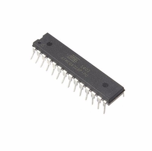
The Atmega328p chip can be programmed in two main ways, assuming it has Arduino bootloader burned on the mcu.
- Using an Arduino Uno
- Using a USB to Serial/TTL Adapter
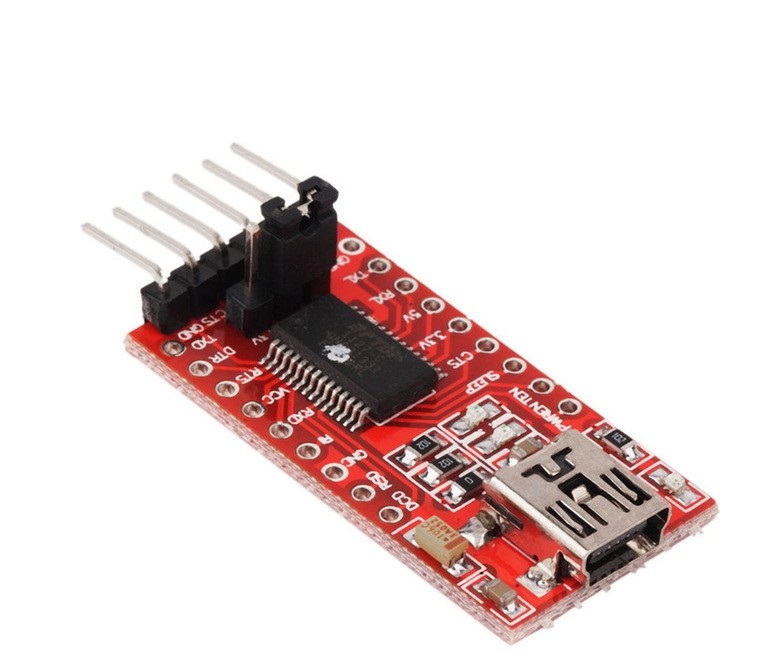
The first way of programming the chip is the easiest as all we need to do is insert the chip into the Arduino Uno, upload the code and move it from the Arduino to our project when ready. The second option is used when there is no Arduino board. A USB to Serial adapter (an example is shown below) is connected directly to the microcontroller to program it via the Arduino IDE.
To program the Atmega328p using any of the methods mentioned above, it is important that the microcontroller is flashed with the Arduino bootloader. The Arduino bootloader is the code that facilitates programming the Atmeg328p chip’s memory using Arduino IDE. A detailed tutorial on how the Arduino bootloader works and how the Atmega328p can be flashed with it can be found here.
To demonstrate how to use the Atmeg328p microcontroller in projects to achieve low power consumption, we will make an upgrade to one of our Arduino weather stations project which was built to last a month initially running on AA batteries. Now we are going to make it last a year using the Atmeg328p microcontroller.
The weather station comprises by the BH1750, BMP180, DHT22 and Nokia 5110 LCD display. The BH1750 sensor is used to measure the light intensity, BMP180 to measure barometric pressure, DHT22 to measure temperature and humidity and all the measured data will be displayed on a Nokia 5110 LCD display.
Required Components
The following components are needed to build this project;
- ATMEGA328
- 16Mhz Crystal
- NOKIA 5110 DISPLAY
- BMP180
- BH1750
- DHT22
- Large Breadboard
- FTDI programmer
- Jumper wires
- Battery Case
- Multimeter
- Wires
- Cheap Arduino Uno
- Batteries
As usual, all the components listed above can be purchased via the link attached to them.
Schematics
Connect the components as shown in the schematics below.
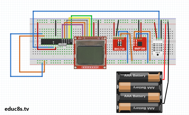
The schematics start with the connection of the crystal oscillator to pin x1 and x2 of the microcontroller after which, each of the other components are connected. The connections between the other components and the Atmeg328p are shown below as a pin map.
Nokia 5110 – Atmega328p
Pin 1(RST) – D13
Pin 2(CE) – D12
Pin 3(DC) – D11
Pin 4(DIN) – D10
Pin 5(CLK) – D9
Pin 6(VCC) - VCC
Pin 7(LIGHT) - GND
Pin 8(GND) - GND
DHT22 – Atmeg328p
VCC - 5v
GND - GND
Signal - D4
DH1750 – Atmeg238p
SDA - A4
SCL - A5
GND - GND
VCC - 5V
BMP180 – Atemg328p
VCC - 5V
GND - GND
SDA - A4
SCL - A5
The DH1750 is an I2C based sensor, this is why it is connected to the same line as the BMP180 as they are both I2C based sensors.
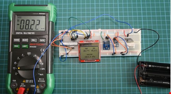
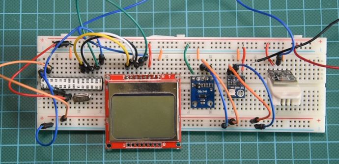
After connecting the components on the breadboard, the setup should look like the image below.
Code
In hardware design and development, power management is done both from the hardware end by choosing low power components and from the software end by powering down internal microcontroller peripherals when they are not needed and other things like adjusting the voltage and frequency to ensure they meet the standard requirements. To reduce power consumption from the software (firmware) side of the device, we will use the Arduino low-power.h library. This library allows us to shut down internal peripherals of the microcontroller using time or via the use of interrupts.
Asides the low-power.h library, the Nokia 5110 LCD library, and library for the BMP180, BH1750 and DHT 22 will be used to easily interface the sensors with the Arduino.
To briefly explain the code for this project, we start by including all the libraries that will be needed as mentioned above.
//Written by Nick Koumaris
//info@educ8s.tv
//educ8s.tv
#include <BH1750.h>
#include "DHT.h"
#include <SFE_BMP180.h>
#include <Wire.h>
#include <LCD5110_Graph.h>
#include "LowPower.h"
Next, we specify the Arduino equivalent of the pins of the atmega328p to which the DHT sensor is connected as arguments after which we create an instance of the DHT library specifying that we are using the DHT22.
#define DHTPIN 4

#define DHTTYPE DHT22
Next, we create an object of the LCD class with the Arduino equivalent pins of atmega328p to which the LCD is connected as arguments after which we also create an object of the BMP180 class. With this done we then create some fonts to use for the display of data on the LCD.
LCD5110 lcd(9,10,11,13,12);

SFE_BMP180 pressure;
extern unsigned char SmallFont[];
extern unsigned char TinyFont[]
Up next is the void setup function under which we initialize the LCD, the light intensity sensor, and the pressure sensor.
void setup(void) {
  initLCD();
  lightMeter.begin();
  pressure.begin();
}
The void loop() function is quite simple. we start by reading the light intensity, if the light intensity is above 30 lumens indicating daytime, we take the readings from other sensors and display them on the LCD. Using the low power library the function sleepfortwominutes() was created. This function shuts down all the hardware peripherals after a reading has been obtained preserving the battery life of the system setup.
void loop() {

 float humidity, pressure;
 readLight();
 if(lightIntensity>30)
 {
 lcd.disableSleep();
 dht.begin();
 delay(400);
 humidity = dht.readHumidity();
 temperature = dht.readTemperature();
 pressure = readPressure();

 lcd.clrScr();
 char tempF[6];
 char humF[6];
 char pressF[7];

 dtostrf(temperature, 5, 1, tempF);
 dtostrf(humidity, 5, 1, humF);
 dtostrf(pressure, 5, 1, pressF);

  //Print UI
  lcd.setFont(TinyFont);
  lcd.print("TEMP",LEFT+17,0);
  lcd.print("HUM",LEFT+62,0);
  lcd.print("PRESSURE",CENTER,30);

  lcd.setFont(SmallFont);
  //Printing Temperature
  lcd.print(tempF,LEFT,10);
  lcd.print("~C",LEFT+30,10);

  //Printing Humidity
  lcd.print(humF,LEFT+45,10);
  lcd.print("%",RIGHT,10);

  //Printing Pressure
  lcd.print(pressF,12,40);
  lcd.print(" hPa",48,40);

  lcd.update();

  sleepForTwoMinutes();
 }else
 {
    lcd.enableSleep();
    sleepForTwoMinutes();
 }
}
The complete code for the project is available for download under the section towards the end of this page.
Demo
Insert the Atmega328P microcontroller into an Arduino and upload the code. After uploading the code, remove the microcontroller and insert it correctly into the circuit on the breadboard.
While we can not wait for a year to confirm that this project will have a battery life longer than 1 year, we can measure the system’s current consumption and use that data to estimate how long a battery will last.
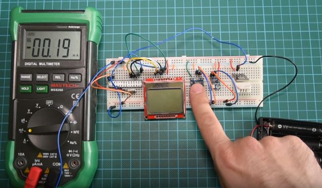
In sleep mode with the screen off, the current draw of the system was o.19mA
With the LCD on and the microcontroller in sleep mode, the current draw was 0.41 mA.
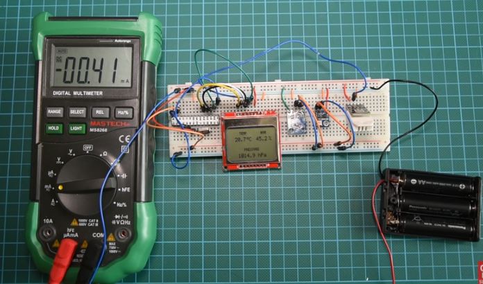
When the system is fully powered, with the microcontroller reading data from sensors, the current draw is 8.22mA
Using the excel sheet attached alongside the code and schematics under the download section, we can see that the system would last for a year running on batteries due to the amount of energy we save by occasionally putting the microcontroller to sleep.
That’s it for this tutorial guys, thanks for taking time to read through. Feel free to drop whatever questions you might have regarding this project under the comment section. I will do my best to provide answers.
The video tutorial for this project is located here.


