Infrared Thermometer with Arduino and MLX90614 Temperature Sensor
- Nick Koumaris
- https://educ8s.tv
- info@educ8s.tv
- 46.658 Views
- medium
- Tested
Most of the temperature measurement techniques around the world require some sort of physical contact between the temperature sensor and the object or environment whose temperature is to be measured, but as technology advanced, this changed too. The need to be able to measure the temperature of an object without physical contact arose. This need brought the measurement of temperature using infrared sensors.
The principle of operation of Infrared thermometers is simple, all bodies at a temperature above 0 Kelvin (absolute zero) emit an infrared energy which can be detected by the infrared thermometer sensor. It’s design includes a lens that focuses the infrared energy being emitted by the object in front of a detector. The detector converts the energy into an electrical signal which then can be passed to a microcontroller to interpret and display in units of temperature after compensating for the variation in ambient temperature.
Today, we will build a DIY Infrared based thermometer using an Arduino Uno, the MLX90614 IR temperature sensor, and a Nokia 5110 LCD display shield to display the measured temperature.
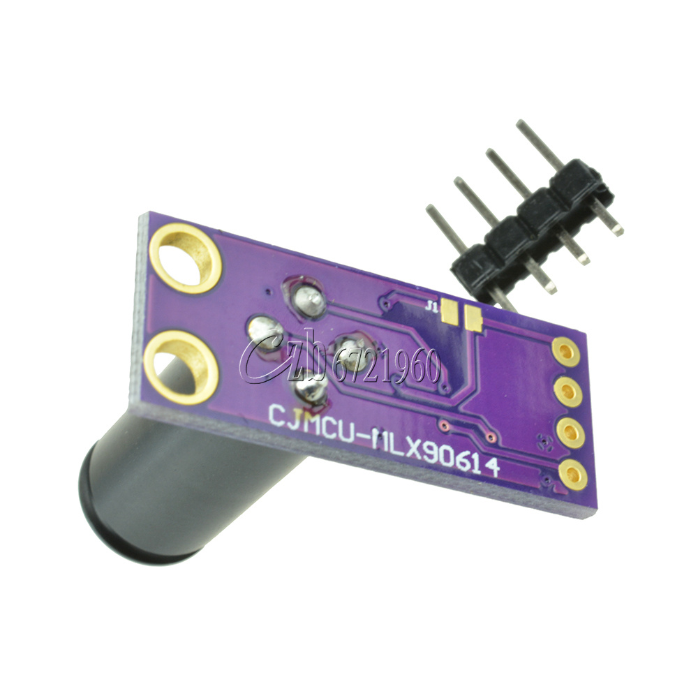
The MLX90614 is an infrared temperature sensor for non-contact temperature measurement. It can measure temperatures within the range of -70 to 380 degree Celsius with an accuracy of about 0.5C at room temperature.
Some of the features of this sensor are listed below:
- Small size and low cost
- Easy to integrate
- Factory calibrated in wide temperature range: -40 to 125°C for sensor temperature and -70 to 380°C for object temperature
- High accuracy of 0.5°C over a wide temperature range (0..+50 C for both Ta and To)
- Measurement resolution of 0.02°C
- Single and dual-zone versions
- SMBus compatible digital interface for fast temperature readings and building sensor networks
- Customizable PWM output for continuous reading
- Available in 3V and 5V versions
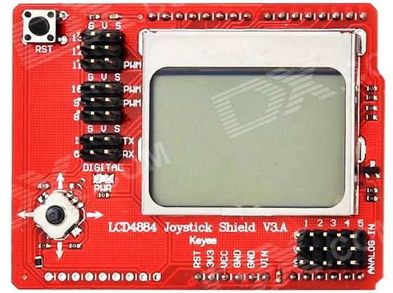
For this tutorial also, for the first time, we will use the Nokia 5110 LCD shield, while we have used the other version of the display several times we have never used the shield version. The shield comes with a joystick and a button. It is pin compatible with the Arduino Uno and most other Arduino boards.
Required Components
The following components are required to build this project:
As usual, the exact components used in this tutorial can be bought via the links attached to each of the components above.
Schematics
The schematics for this project is very easy because the display comes as a shield which takes away the need to connect it via wire and all we need to do is to plug the display on the Arduino. The connection between the Arduino and the temperature sensor is shown in the schematics below.
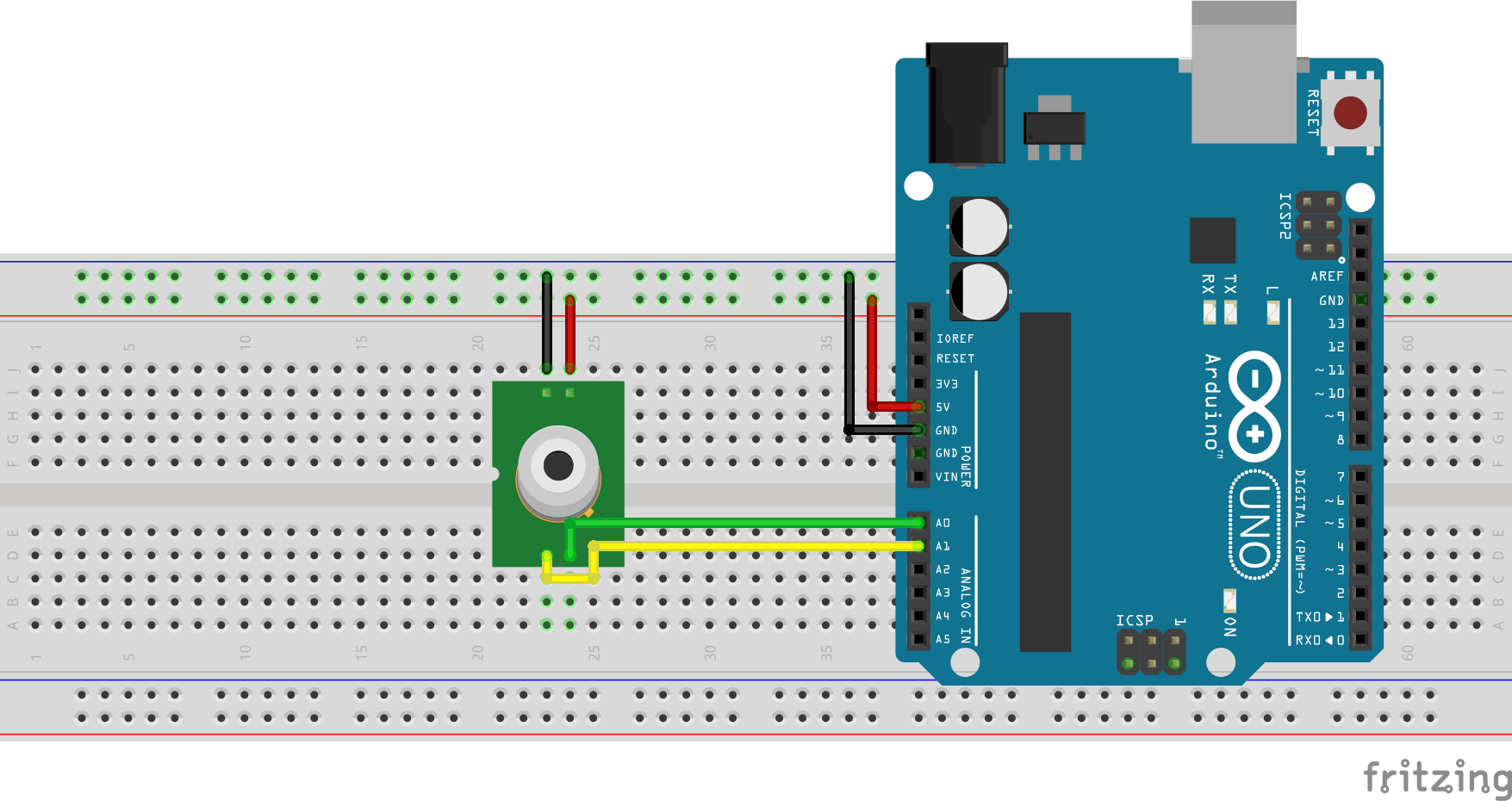
To make the connections easier to follow, the connection is further detailed below.
MLX90614 – Arduino Uno
VCC  - 5V
GND  -  GND
SCL  - A5
SDA  - A4
Go over the connection once again to ensure everything is as it should be.
Code
Our goal for this project is to measure the temperature, process it and display it on the LCD. To enable us to communicate easily with the mlx90614 temperature sensor, we will use the mlx90614 temperature sensor library from Adafruit and the Nokia 5110 LCD graph library for easy display of text on the screen. The libraries can be downloaded via the link attached to each of the libraries in the sentence above.
To briefly explain the code for the project, we start as usual by including all the libraries that will be needed in the code.
# Written by Nick Koumaris
# info@educ8s.tv

#include <LCD5110_Graph.h>
#include <Wire.h>
#include <Adafruit_MLX90614.h>=
Next, we create an object of the LCD library, specifying the pins of the Arduino to which the LCD pins are connected.
LCD5110 lcd(2,3,4,6,5); //Use this line with the shield
With this done, we create variables for the fonts and other elements that are needed for the display after which we create an instance of the temperature sensor.
char TEMPERATURE = 'C';

extern uint8_t SmallFont[];
extern uint8_t BigNumbers[];
extern uint8_t uic[];
extern uint8_t uif[];
extern uint8_t splash[];

Adafruit_MLX90614 mlx = Adafruit_MLX90614();
Next, we write the void setup function. We start the code by initializing the LCD and temperature sensor after which we use the LCD.drawbitmap() to create the user interface on the display. The interface had already been designed and converted into a C-file and is already attached to the code. The reason for using the UI is to be able to display the data in a more user-friendly and efficient way. We have done a lot of tutorials in the past that show how to create custom graphics for the Nokia 5110 LCD display. One of such tutorials can be accessed here.
void setup()
{
  Serial.begin(9600);
  lcd.InitLCD(60);
  mlx.begin();
  lcd.drawBitmap(0, 0, splash, 84, 48);
  lcd.update();
  delay(3000);
}
Next, is the void loop function. The scope of the void loop function is simple. We start by determining the unit of measurement in which the temperature is to be displayed either in Celsius or in Fahrenheit, then we read the temperature from the temperature sensor and display it on the display. For accuracy, a time delay of 1000ms as inserted in between readings to ensure and prevent read requests from clashing.
void loop()
{
  String temperature="";
  lcd.clrScr();

  if(TEMPERATURE == 'C')
  {
     temperature = String(mlx.readObjectTempC(),1);
     lcd.drawBitmap(0, 0, uic, 84, 48);
  }else
  {
     temperature = String(mlx.readObjectTempF(),1);
     lcd.drawBitmap(0, 0, uif, 84, 48);
  }

  if(temperature.length()>4)
  {
    temperature.remove(3,2);
  }

  Serial.println(temperature);
  lcd.setFont(BigNumbers);

  if(temperature.length()==4)
  {
    lcd.print(temperature,5,19);
  }else
  {
    lcd.print(temperature,15,19);
  }
The complete code for the project is attached to the download section at the bottom of the page.
Demo
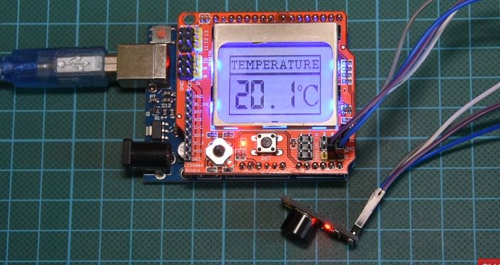
Ensure the project is wired up as described in the schematics section. Copy the code and upload to the Arduino board, then point the temperature sensor to an object whose temperature you wish to measure. After a while, the temperature of that object will be shown on the screen.
Asides non-contact temperature, the MLX90614 IR temperature sensor can also be used to measure the ambient temperature but we won’t be considering that for this tutorial.
Some of the major applications of this project include:
- Heating and air conditioning
- Systems monitoring – Monitoring the performance of cooling systems, boiler operations, steam systems and detection of hot spots in electrical/electronics systems and panels
- Agriculture – Monitoring the temperature at which food is being processed and stored
That’s it for this tutorial guys, do let me know via the comment section if you have any questions. The video version of the tutorial can be watched on youtube here.




Much like in Star Trek from time to time, there is no such thing as “0°Kelvin”, or any degree of Kelvin. Celcius and Farenheit can be expressed using degrees but not Kelvin. And please stick to using either written degrees or ° (0176), not both.
Thanks for the note. We fixed this on the article.
When use Gy-mcu90615 the communication protocol will change..so the arduino code will be change also? Do you have the code when use Gy-mcu90615? Thanks in advance
What’s the range on the sensor? How far away can it sense a fire for example? Can it be used to locate the location of a heat source?