ESP8266 WiFi Air Conditioner Remote Control
- Emmanuel Odunlade
- https://twitter.com/emmaodunlade
- emmaodunlade@gmail.com
- 41.732 Views
- advanced
- Tested
We recently started exploring the ESP8266 boards and today’s project is going to be an interesting one based on this WiFi module. We are going to build an ESP8266 based WiFi Air condition Remote Controller. While this project can be adapted to fit any device that uses a remote control, we will use it for controlling an Air Conditioner.
Usually, everyone switches “OFF” all electrical appliances in their home, including Air conditioners when leaving the house, this means when you get back home, the temperature will not be regulated, and it will take the air conditioner some time to achieve your desired level of coolness. But what if you could automatically control your air conditioner from your mobile phone when you are a few blocks away from home? What if you could turn it OFF from wherever you are, if you discover you left it ON when leaving the house? What if it can be synced with your phone’s location and turned ON when you are almost home? What if it can be synced with the weather information of your phone? These and many more questions, inspired today’s project.
How it works
The air conditioner (AC), is normally controlled by a “remote control” which sends infrared signals to it when a button is pressed. The AC interprets the signals and converts them to instructions to either increase its coolness or reduce it, go OFF or come ON, etc. Thus to be able to control it using our own device, the device will have to be able to mimic and send the same signals sent by the remote to the AC, such that, by pressing the “ON” button (as an example) on the app, our WiFi remote control sends the same IR signal the remote would have sent if the “ON” button was pressed.
The device we are going to build is based on the ESP8266 and it’s wonderful features and use has been discussed in one of our past tutorials. The ESP8266 will be connected via MQTT to home bridge and through it, Siri can be used to give instructions to control the AC. Once the instruction (say “turn on” for instance) is received over MQTT, the NodeMCU matches it with corresponding IR signals and the signal is sent to the AC through an IR led. An OLED display is used to provide visual feedback about the current state to the user. For non-iPhone users, the device can also be connected to the Amazon Alexa.
Asides the control of the Air conditioner via Siri or Apple’s home kit, it is also equipped with control switches.
To make the experience a complete one, the following features were added to the project;
- Display NTP Clock when standby.
- Simple button control. Power, Temp up / down.
- Can control temperature, swing, fan speed and mode with HomeKit.
- Auto brightness according to ambient light.
- OTA Firmware upgrade.
- Control via HomeKit using HeaterCooler Service (iOS 11+)
- Works with Amazon Alexa using fan service
At the end of today’s tutorial, you would know the basics of building IoT solutions and Home automation. You would also learn how to intercept signals sent by IR based remote controls, ( please do this within lawful limits and do not apply to dangerous situations), create an IR transmitter which could be used to control all IR remotes based appliances in your home or office, and build devices that can be controlled via Apple’s Home kit.
Required Components
The following components are needed for this tutorial;
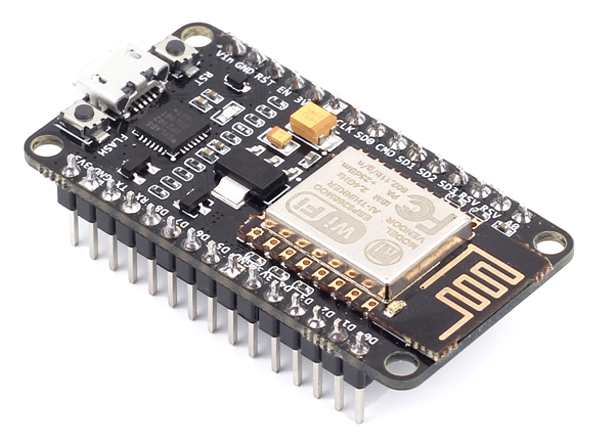
- ESP8266 NodeMCU
- Raspberry Pi 4, or Raspberry Pi 3 or Raspberry Pi 2 with a WiFi dongle
- Keyboard, Monitor, and HDMI cable for the Pi or a LAN cable (for headless mode connection)
- 2A Power supply for the Raspberry Pi
- SSD1332 OLED Display (256 × 64)
- LDR
- Push button
- IR LED
- LED
- 1k resistor (4)
- NPN Transistor BC338
- Jumper wires
- Breadboard
- TSOP 1738
- Veroboard
The LDR is not compulsory as it was used to dim or turn off the backlight and make the OLED screen easier to read.
Schematics
As mentioned in the project description, the hardware part of the project itself is made up of the NodeMCU, an IR LED, some push-buttons and an OLED Display.
Connect the components as shown in the schematics below.

The push-buttons provide an alternative way of controlling the device when you are not carrying your mobile phone, and the OLED display provides diverse information including the current temperature being maintained by the AC.
Another view of the schematics is provided below to make it easier to follow.
Preparing the System
Before we write the code for the project, we need to make some preliminary preparations.
- Prepare the IR signals that will be sent to the AC for each command
- Setup Communication with Homekit
1. Decoding the IR signals
As mentioned above, this project works by mimicking the IR remote, sending out IR signals generated based on the commands from Homekit. Since the IR signals have to be the same as the one sent by the remote, we need to obtain the IR code for each button before anything else. To obtain the codes, we have to build a device which receives the IR signal from the remote control, decodes it and displays the encoded data so we can copy it for use later on.
To obtain the IR codes, we will use the cheap, efficient and popular TSOP1738 IR receiver, connected to Nodemcu, in the way that when a button on the remote is pressed, the IR receiver will pick it and through the decode sketch running on the NodeMCU, it will print the content of the signal on the serial monitor. This content will be later used to control the AC.
Schematics
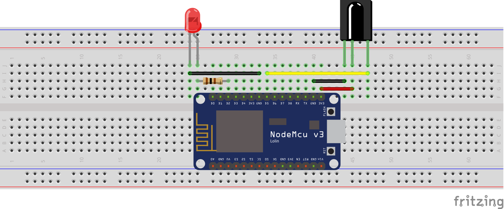
Connect the IR receiver to the NodeMCU as shown in the image below:
To determine when an IR signal is received and help us for debug, a LED was added in the schematics so that it only comes on when an IR signal is received.
Here is a pin map of the connection between the NodeMCU and the TSOP;
ESP8266 - TSOP1738
GND - GND
3.3V - VCC
D5 - Signal
Code
Today’s project is heavily dependent on the IRremote ESP8266 library, which can be downloaded from the link attached. The library is based on the standard Arduino IRremote library and comes with the decoded data (for few common keys), for quite a number of popular remote controls, which means that you could be lucky, and the codes for your remote will be already available in the library. For those that are not so lucky, along with the schematics above, we will use the example sketch, IRrecvDumpV2 which comes with the IRremote ESP8266 library to obtain the codes.
With the library installed, launch the Arduino IDE, go to examples and select the IRrecvDumpV2 example. Upload the code to your NodeMcu and press a button on your remote control. You should see an array of numbers show up in the serial monitor every time a button on the remote is pressed. Copy and keep the array for each key as they represent the decoded IR signals sent by the remote and we will use them to reproduce the IR signal for our Air conditioner. The code is well commented and should be easy to follow.
2. Connecting with Homekit
The second thing we need to do before writing the code is setting up the connection to Homekit. Connection to Homekit gives us the ability to control the device using Siri and the Homekit app. To achieve this, we will use the Homebridge-MQTT installed on a RaspberryPi which will serve as our server. The Homebridg-MQTT is essentially a plugin for homebridge that allows you to add and control devices via the MQTT protocol.
Boot up your RaspberryPi and open a terminal. We will start by updating the Pi to ensure we don’t run into any compatibility issue later on.
Run:
Sudo apt-get update
with this done, Install MOSQUITTO on the pi for MQTT. run;
sudo apt-get install mosquitto
once this is done, install the Homebridge-MQTT plugin using;
sudo npm install -g homebridge-mqtt
Next, we need to edit the config file. the config file is located inside the homebridge folder (home / .homebridge /config.js). Change into the directory and run;
sudo nano config.js
Add the platform section to the config file such that it now looks like this;
 {
     "bridge": {
     "name": "Homebridge",
     "username": "CC: 22: 3D: E3: CE: 30",
     "port": 51826,
     "pin": "031-45-154"
},
"description": "This file is a fake accessory and one fake platform.",
"accessories": [{
     "accessory": "relay",
     "name": "My relay light 1",
     "pin": 7
     }],
"platforms": [{
     "platform": "mqtt",
     "name": "mqtt",
     "url": "mqtt: //127.0.0.1",
     "port": "1883",
     "topic_type": "multiple",
     "topic_prefix": "homebridge",
     "qos": 1
     }]
}
save the config file and exit.
Run HomeBridge, use MQTT LENS (can be downloaded from Chrome Webstore) and add Connection to our Raspberry Pi, creating an accessory that uses the heater-cooler service which is supported by any version of the IoS from IOS11. Set the publish to value as;
homebridge / to / add
and set the payload as;
 {
  "name": "Smart AC",
  "service_name": "smart_ac",
  "service": "HeaterCooler",
  "manufacturer": "ESP8266",
  "firmwarerevision": "1.0.0",
  "SwingMode": 1,
  "RotationSpeed": {"maxValue": 3, "minValue": 0, "minStep": 3},
 "CoolingThresholdTemperature": {"maxValue": 28, "minValue": 18, "minStep": 1}
}
With all these done, we can now proceed to write the code for this project.
Code
The code for today’s project will be developed using VScode and the platform.io IDE plugin. The code is quite bulky and may be difficult to follow for anyone not used to programming microcontrollers using these tools so we wrote a simple tutorial on using these tools, be sure to check it out.
As mentioned earlier, the code for today’s project is heavily reliant on the IRremoteESP8266 library, but it also utilizes the Wifi manager library, the Arduinojson library, the Arduino OTA library, and the NTP library. Each of these libraries made it easy to achieve different parts of the project. The IRremoteESP8266 library was used to send IR signals from the device to the Air conditioner, the Wifimanager library was used to make it easy to change the WiFi credentials, the Arduinojson was used to parse the data from homekit and the Arduino OTA library was used to enable over the air firmware update on the device. Other libraries used include U8g2 library which makes it easy to work with monochrome displays. It was used to display the graphics which formed the UI for the project. All the libraries used for this project can be downloaded and installed via the Arduino library manager.
The code for this project is quite bulky and may be too much to explain here but we have ensured it is well commented and attached in the zip file under the download section. The zip file contains a bunch of files including the graphics images used for the GUI, the libraries, and everything about the project. The code is located in the “src” folder. The “src folder also contain different codes most of which are header files for the main code-named main.cpp. All other files are important and need to be in the same project folder as the main.cpp as they contain all the information needed by the main file. For instance, main.h file, contains the MQTT declarations among other things while the UI.h file contains the char values of everything used for the UI.
For those who may be interested in creating their own UI for the project, check out this tutorial we created a while back. It might give you the necessary start point.
Enclosure
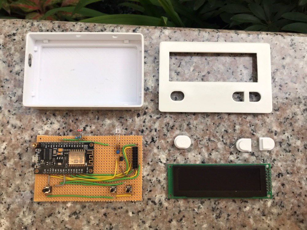
To make the project look pleasing to the eye, an enclosure was 3D printed. The design was done using Fusion 360 and all the design files are included n the zip file under the download section.
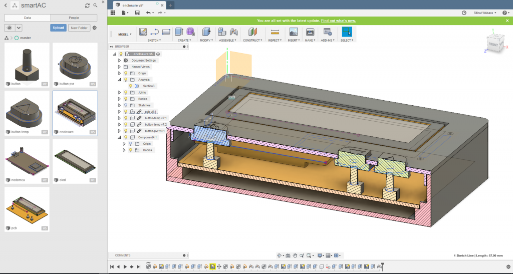
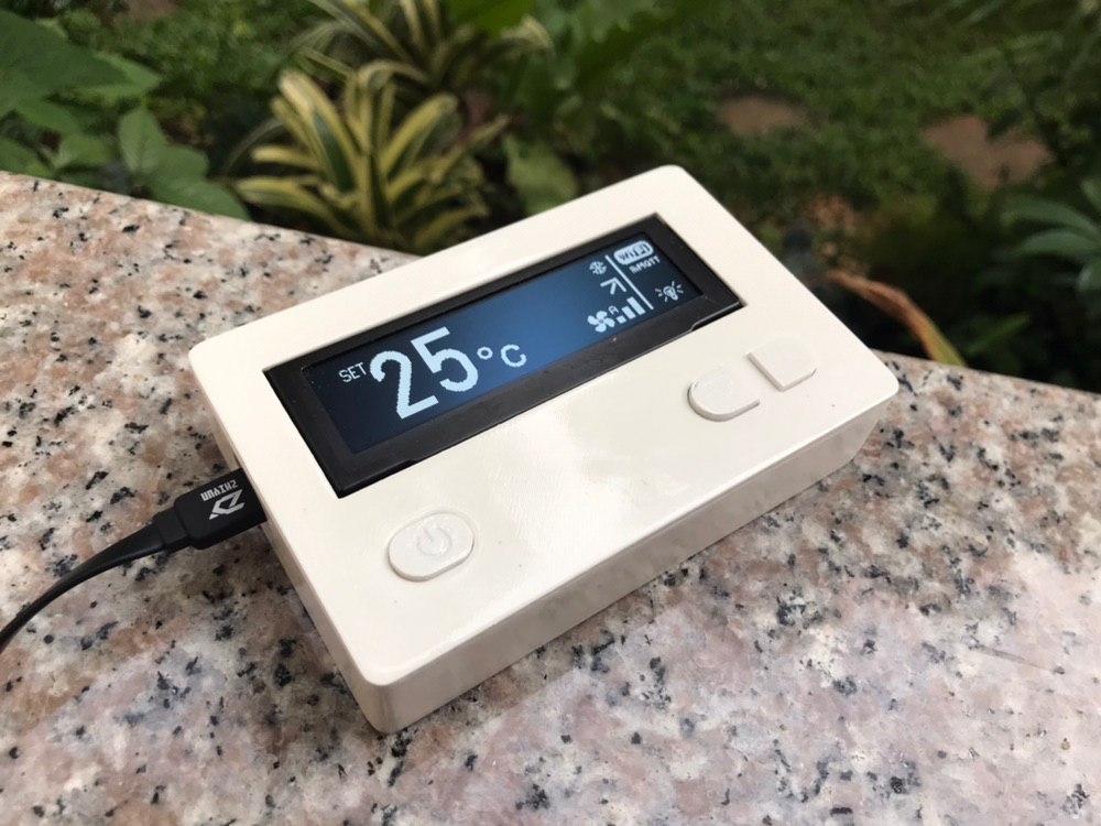
After printing, the enclosure was scrubbed and painted to make the print look better. The final enclosure is shown in the image below.
Demo
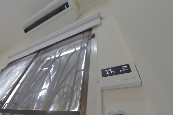
Ensure that the connections are as described and switch on your device. It should come up as shown in the picture below.
That’s it for this tutorial guys. As said in the beginning, the applications for this project are limitless. It can serve as a simple box that controls every IR remote controlled device in your house. Do let me know if you have questions and what cool ideas you will be implementing with all you have learned here.
Till next time.
A video of the device in action can be seen below:
Sources:
- Picture Credits: MaxMac
- Source Code: Github
- Enclosure Cad file: Autodeskhub
- Others: MaxMac




i want code for decoding the siganls and sent that to ir led at a time
Hi my friend! Than you for your amazing project. I want to ask you how to make the project working with Alexa? Do I need a new skill to make? Thank you.
will u please share me the code for decoding and sending the ir signals ????
Hi Prasanth,
the code for that is an example sketch in the IRremoteESP8266 library ( https://github.com/markszabo/IRremoteESP8266 ). Check the IRrecvDumpV2 example. You should be able to use that to decode the IR signals.
To send the IR signals, check the attached zip file for the exact one used for this tutorial. If you are building something different from this tutorial, check the IRremoteESP8266 library and adapt the IRsendDemo example for your use.
Hi. Can send me links to parts where to buy all that stuff.. Specially oled display with that correct connector.
Is there ready set of pins to put on oled? And what part is is that black connector to oled on board?
Hi, Rhead, Will attach links to where you can buy the components now.
I can’t seem to figure out where the raspberry pi has been used
Homekit MQTT was installed on the Pi. Check the second subtopic under the “preparing the system” section, i.e. “Connecting with Homekit”
Can’t I do this through my PC, it has Linux Mint installed
You can ofcourse but Raspberry pi 3 and above has wifi built in and can be placed anywhere out of sight as long as its connected to wifi. Imo its better as a gateway to your iot device at home to the internet rather than having a laptop or pc stay on 24/7
Friend very good job. I would like to add some add-ons. It would be possible for you to share the FUSION files
The 3D files are available on MQTT-AC-Controller-master-1.zip under downloads in this page.
Hi. Do you have schematics to for SSD1332 OLED Display (256 × 64) how to connect? Because schematics pictures different size and connection of oled.
Awesome! Curious on how long it lasts on a 9V battery?
When I load the code and then set the Network settings through the AP it constantly reboots, this is just with the Nodemcu connected, does it need to have all the components connected to stay booted up?