ESP32 Webserver Tutorial
- Emmanuel Odunlade
- https://twitter.com/emmaodunlade
- emmaodunlade@gmail.com
- 37.004 Views
- moderate
- Tested
One of the most interesting project we can build while learning to work with a WiFi Based board is a web Server. As we continue the journey to learn how to build projects with the ESP32, we will examine how to build a simple web Server with the ESP32.
A Web server is essentially a device which stores, processes and delivers web pages to web clients, which can range from browsers on our laptops to Mobile apps on our smartphones. The communication between client and server takes place using a special protocol called Hypertext Transfer Protocol (HTTP). The client uses an URL to make a request for a particular page and the server responds with the content of that web page or an error message if the page is not available.
In our case, rather than responding with a specific webpage, the URL will be used to control the state of LEDs connected to the ESP and the changes made will be updated on the webpage. For instance, if a URL like “http://192.168.1.1/ledon” is entered in the browser, the web server will understand its time to turn the LED “ON” and then update the status of the LED to “ON” on the webpage. Same thing will happen when it’s required to go “OFF”.
At the end of today’s tutorial, you would know how to set up a web server on the ESP32 and connect to it via a client (Webpage) to control its GPIO pins.
Required Components
The following components are required for this project:
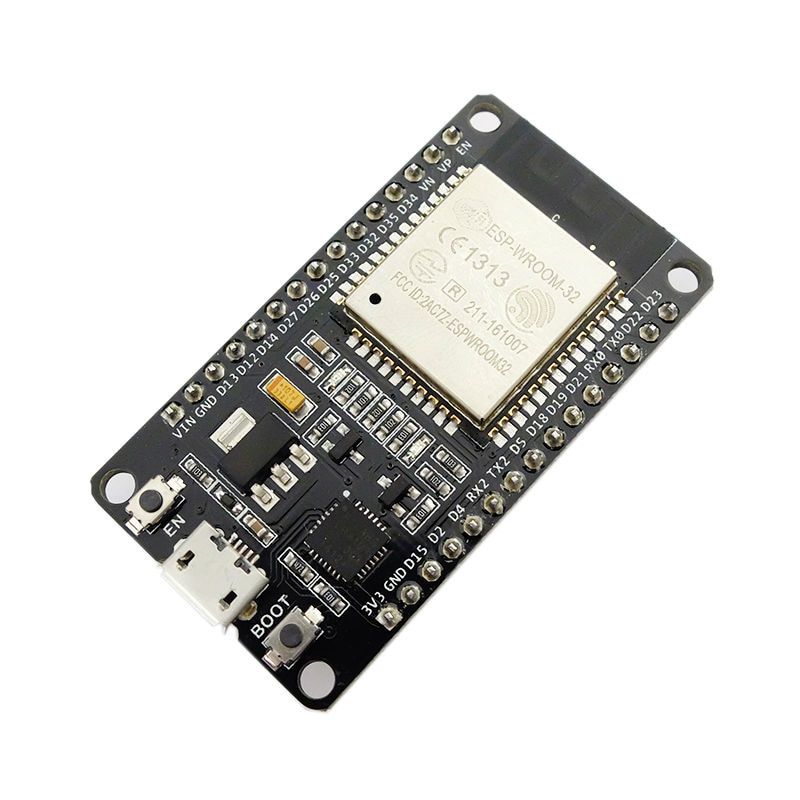
- DOIT ESP32 DEVKIT V1
- 220 ohms Resistor (2)
- LED (2)
- Breadboard
- Jumper Wire
The DOIT Devkit V1 ESP32 board is used for this tutorial due to its obvious popularity among makers. Feel free to use any of the other ESP32 based boards for the project.
Schematics
The schematics for this tutorial is quite simple. As mentioned earlier, we will toggle LEDs to demonstrate what can be achieved using the NodeMCU Web server and while LEDs are being used here, you can decide to use more useful components like a relay, which could give you the ability to remotely control appliances in your home. Connect the components as shown below.
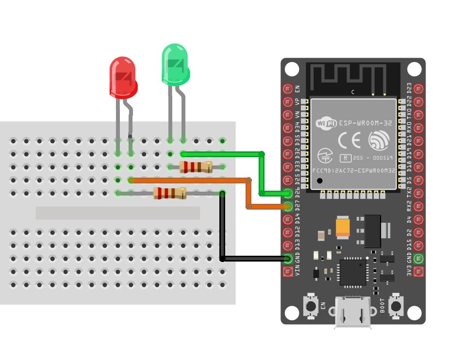
The positive legs of the green and red LEDs are connected t0 GPIO pins 26 and 27 on the ESP32 (respectively), while their negative legs are connected to ground via a 220 ohms resistor to limit the amount of current flowing through the LEDs.
With the schematics done, we can now move to the code for the project.
Code
We will use the Arduino IDE to develop the sketch for today’s project due to its versatility, huge support, and popularity. To be able to do this, you need to install the ESP32 board support files on the Arduino IDE. We covered this in the ESP32 introduction tutorial that was published a few weeks back, so be sure to check it out.
The sketch for this tutorial is fairly easy. The algorithm involves us connecting the ESP32 to an access point and generating an IP address through which devices connected to the ESP can access the web server. The client (a webpage running on connected devices), in connection to the server, is serving a webpage that has buttons to control the LEDs and a function is placed behind the buttons to handle the actions that occur when they are clicked.
To reduce the amount of code we need to write, we will use the ESP32 WiFi Library. The library contains functions that make setting up the ESP32 as a web server easy. The library, along with several others, is packaged together with the ESP32 board files and are automatically installed when the ESP32 board files are installed on the Arduino IDE.
The code is an adaptation of the code for a similar Project by Rui Santos and an old ESP8266 webserver tutorial we wrote. You can check that out for better understanding.
To do a brief explanation, we start as usual, by including the library required for the project, which in this case, is just the WiFi.h library.
#include <WiFi.h>
#include <WiFi.h>
#include <WiFi.h>
Next, add the credentials of the WiFi access point to which the ESP32 will be connected. Ensure the username and password are in-between the double quotes. We also specify the port through which the system will communicate and create a variable to hold requests.
// Replace with your network credentials
const char* ssid     = "Enter_SSID_here";
const char* password = "Enter_Password_here";

// Set web server port number to 80
WiFiServer server(80);

// Variable to store the HTTP request
String header;
// Replace with your network credentials
const char* ssid = "Enter_SSID_here";
const char* password = "Enter_Password_here";
// Set web server port number to 80
WiFiServer server(80);
// Variable to store the HTTP request
String header;
// Replace with your network credentials const char* ssid = "Enter_SSID_here"; const char* password = "Enter_Password_here"; // Set web server port number to 80 WiFiServer server(80); // Variable to store the HTTP request String header;
Next, we declare the pins of the ESP32 to which the red and green LED are connected and create variables to hold the state of the LEDs.
int greenled = 26;
int redled = 27;

String greenstate = "off";// state of green LED
String redstate = "off";// state of red LED
int greenled = 26;
int redled = 27;
String greenstate = "off";// state of green LED
String redstate = "off";// state of red LED
int greenled = 26; int redled = 27; String greenstate = "off";// state of green LED String redstate = "off";// state of red LED
With this done, we move to the void setup() function.
We start by initializing the serial monitor (it will be used for debugging later) and set the pinModes of the pins to which the LEDs are connected as outputs. We then set the pins “LOW” to ensure the system starts at a neutral state.
void setup() {
  Serial.begin(115200);
 // Set the pinmode of the pins to which the LEDs are connected and turn them low to prevent flunctuations
  pinMode(greenled, OUTPUT);
  pinMode(redled, OUTPUT);
  digitalWrite(greenled, LOW);
  digitalWrite(redled, LOW);
void setup() {
Serial.begin(115200);
// Set the pinmode of the pins to which the LEDs are connected and turn them low to prevent flunctuations
pinMode(greenled, OUTPUT);
pinMode(redled, OUTPUT);
digitalWrite(greenled, LOW);
digitalWrite(redled, LOW);
void setup() {
Serial.begin(115200);
// Set the pinmode of the pins to which the LEDs are connected and turn them low to prevent flunctuations
pinMode(greenled, OUTPUT);
pinMode(redled, OUTPUT);
digitalWrite(greenled, LOW);
digitalWrite(redled, LOW);
Next, we connect to the access point using the credentials as arguments to the WiFi.begin() function and the WiFi.status() function to check if connection was successful.
WiFi.begin(ssid, password);
Serial.print("Connecting to ");
Serial.println(ssid);
while (WiFi.status() != WL_CONNECTED) {
  delay(500);
  Serial.print(".");
}
WiFi.begin(ssid, password);
Serial.print("Connecting to ");
Serial.println(ssid);
while (WiFi.status() != WL_CONNECTED) {
delay(500);
Serial.print(".");
}
WiFi.begin(ssid, password);
Serial.print("Connecting to ");
Serial.println(ssid);
while (WiFi.status() != WL_CONNECTED) {
delay(500);
Serial.print(".");
}
If the connection is successful, a text is printed on the serial monitor to indicate that, and the IP address of the web server is also displayed. This IP address becomes the web address for the server and it is what we need to enter on any web browser on the same network to access the Server.
Serial.println("");
Serial.println("WiFi connected.");
Serial.println("IP address: ");
Serial.println(WiFi.localIP());// this will display the Ip address of the Pi which should be entered into your browser
Serial.println("");
Serial.println("WiFi connected.");
Serial.println("IP address: ");
Serial.println(WiFi.localIP());// this will display the Ip address of the Pi which should be entered into your browser
Serial.println("");
Serial.println("WiFi connected.");
Serial.println("IP address: ");
Serial.println(WiFi.localIP());// this will display the Ip address of the Pi which should be entered into your browser
With that done, we start the server using the server.begin() function and proceed to the void loop( ) function.
server.begin();
server.begin();
server.begin();
The void loop() function is where the majority of the work is done. We start by using the server.available() function to listen for incoming connection by clients. When a client is available and connected, we read the client request and send a header as a response.
WiFiClient client = server.available();   // Listen for incoming clients

  if (client) {                             // If a new client connects,
    String currentLine = "";                // make a String to hold incoming data from the client
    while (client.connected()) {            // loop while the client's connected
      if (client.available()) {             // if there's bytes to read from the client,
        char c = client.read();             // read a byte, then
        Serial.write(c);                    // print it out the serial monitor
        header += c;
        if (c == '\n') {                    // if the byte is a newline character
          // if the current line is blank, you got two newline characters in a row.
          // that's the end of the client HTTP request, so send a response:
          if (currentLine.length() == 0) {
            // HTTP headers always start with a response code (e.g. HTTP/1.1 200 OK)
            // and a content-type so the client knows what's coming, then a blank line:
            client.println("HTTP/1.1 200 OK");
            client.println("Content-type:text/html");
            client.println("Connection: close");
            client.println();
Next, we check if the client’s request indicates a button press to turn any of the pins “ON/OFF” starting with the green LED. If the request indicates “ON”, the pin is turned high and the state variable is updated accordingly and vice versa.
// turns the GPIOs on and off
           if (header.indexOf("GET /green/on") >= 0) {
             Serial.println("green on");
             greenstate = "on";
             digitalWrite(greenled, HIGH);
           } else if (header.indexOf("GET /green/off") >= 0) {
             Serial.println("green off");
             greenstate = "off";
             digitalWrite(greenled, LOW);
           } else if (header.indexOf("GET /red/on") >= 0) {
             Serial.println("red on");
             redstate = "on";
             digitalWrite(redled, HIGH);
           } else if (header.indexOf("GET /red/off") >= 0) {
             Serial.println("red off");
             redstate = "off";
             digitalWrite(redled, LOW);
           }
Next, we create the webpage that will be displayed and updated by the NodeMCU as the user interacts with it. The key function for this is the Client.println() function which is used to send HTML scripts line by line to the client (browser).
We start by using the “doctype” to indicate that the next few texts to be printed are HTML lines.
client.println("<!DOCTYPE html><html>");
client.println("<!DOCTYPE html><html>");
client.println("<!DOCTYPE html><html>");
Next, we add the lines below to make webpage responsive irrespective of the browser being used.
client.println("<head><meta name=\"viewport\" content=\"width=device-width, initial-scale=1\">");
client.println("<head><meta name=\"viewport\" content=\"width=device-width, initial-scale=1\">");
client.println("<head><meta name=\"viewport\" content=\"width=device-width, initial-scale=1\">");
We also throw in some bits of CSS to the client to make the page user-friendly. You can edit this to add your own color, font style, etc.
client.println("<style>html { font-family: Helvetica; display: inline-block; margin: 0px auto; text-align: center;}");
client.println(".button { background-color: #195B6A; border: none; color: white; padding: 16px 40px;");
client.println("text-decoration: none; font-size: 30px; margin: 2px; cursor: pointer;}");
client.println(".button2 {background-color: #77878A;}</style></head>");
Next, the webpage header is sent alongside the buttons which are set to display ON or OFF based on the current state of the LEDs. It will display OFF if the current state is ON and vice versa.
client.println("<body><h1>ESP32 Web Server</h1>");

// Display current state, and ON/OFF buttons for green LED
client.println("<p>green - State " + greenstate + "</p>");
// If the green LED is off, it displays the ON button
if (greenstate == "off") {
  client.println("<p><a href=\"/green/on\"><button class=\"button\">ON</button></a></p>");
} else {
  client.println("<p><a href=\"/green/off\"><button class=\"button button2\">OFF</button></a></p>");
}

// Display current state, and ON/OFF buttons for Red LED
client.println("<p>red - State " + redstate + "</p>");
// If the red LED is off, it displays the ON button
if (redstate == "off") {
  client.println("<p><a href=\"/red/on\"><button class=\"button\">ON</button></a></p>");
} else {
  client.println("<p><a href=\"/red/off\"><button class=\"button button2\">OFF</button></a></p>");
}
client.println("</body></html>");
Next, we close the connection and the loop goes over again.
// Clear the header variable
header = "";
// Close the connection
client.stop();
Serial.println("Client disconnected.");
Serial.println("");
// Clear the header variable
header = "";
// Close the connection
client.stop();
Serial.println("Client disconnected.");
Serial.println("");
// Clear the header variable
header = "";
// Close the connection
client.stop();
Serial.println("Client disconnected.");
Serial.println("");
The complete code for the project is available below and under the download section of this tutorial.
#include <WiFi.h>

// Replace with your network credentials
const char* ssid = "Enter_SSID_here";
const char* password = "Enter_Password_here";

// Set web server port number to 80

WiFiServer server(80);

// Variable to store the HTTP request String header;
String header;
// Declare the pins to which the LEDs are connected
int greenled = 26;
int redled = 27;

String greenstate = "off";// state of green LED
String redstate = "off";// state of red LED


void setup() {
  Serial.begin(115200);
 // Set the pinmode of the pins to which the LEDs are connected and turn them low to prevent flunctuations
  pinMode(greenled, OUTPUT);
  pinMode(redled, OUTPUT);
  digitalWrite(greenled, LOW);
  digitalWrite(redled, LOW);
  //connect to access point
  WiFi.begin(ssid, password);
  Serial.print("Connecting to ");
  Serial.println(ssid);
  while (WiFi.status() != WL_CONNECTED) {
    delay(500);
    Serial.print(".");
  }
  // Print local IP address and start web server
  Serial.println("");
  Serial.println("WiFi connected.");
  Serial.println("IP address: ");
  Serial.println(WiFi.localIP());// this will display the Ip address of the Pi which should be entered into your browser
  server.begin();
}

void loop(){
  WiFiClient client = server.available();   // Listen for incoming clients

  if (client) {                             // If a new client connects,
    String currentLine = "";                // make a String to hold incoming data from the client
    while (client.connected()) {            // loop while the client's connected
      if (client.available()) {             // if there's bytes to read from the client,
        char c = client.read();             // read a byte, then
        Serial.write(c);                    // print it out the serial monitor
        header += c;
        if (c == '\n') {                    // if the byte is a newline character
          // if the current line is blank, you got two newline characters in a row.
          // that's the end of the client HTTP request, so send a response:
          if (currentLine.length() == 0) {
            // HTTP headers always start with a response code (e.g. HTTP/1.1 200 OK)
            // and a content-type so the client knows what's coming, then a blank line:
            client.println("HTTP/1.1 200 OK");
            client.println("Content-type:text/html");
            client.println("Connection: close");
            client.println();

            // turns the GPIOs on and off
            if (header.indexOf("GET /green/on") >= 0) {
              Serial.println("green on");
              greenstate = "on";
              digitalWrite(greenled, HIGH);
            } else if (header.indexOf("GET /green/off") >= 0) {
              Serial.println("green off");
              greenstate = "off";
              digitalWrite(greenled, LOW);
            } else if (header.indexOf("GET /red/on") >= 0) {
              Serial.println("red on");
              redstate = "on";
              digitalWrite(redled, HIGH);
            } else if (header.indexOf("GET /red/off") >= 0) {
              Serial.println("red off");
              redstate = "off";
              digitalWrite(redled, LOW);
            }

            // Display the HTML web page
            client.println("<!DOCTYPE html><html>");
            client.println("<head><meta name=\"viewport\" content=\"width=device-width, initial-scale=1\">");
            client.println("<link rel=\"icon\" href=\"data:,\">");
            // CSS to style the on/off buttons
            // Feel free to change the background-color and font-size attributes to fit your preferences
            client.println("<style>html { font-family: Helvetica; display: inline-block; margin: 0px auto; text-align: center;}");
            client.println(".button { background-color: #195B6A; border: none; color: white; padding: 16px 40px;");
            client.println("text-decoration: none; font-size: 30px; margin: 2px; cursor: pointer;}");
            client.println(".button2 {background-color: #77878A;}</style></head>");

            // Web Page Heading
            client.println("<body><h1>ESP8266 Web Server</h1>");

            // Display current state, and ON/OFF buttons for GPIO 26
            client.println("<p>green - State " + greenstate + "</p>");
            // If the green LED is off, it displays the ON button
            if (greenstate == "off") {
              client.println("<p><a href=\"/green/on\"><button class=\"button\">ON</button></a></p>");
            } else {
              client.println("<p><a href=\"/green/off\"><button class=\"button button2\">OFF</button></a></p>");
            }

            // Display current state, and ON/OFF buttons for GPIO 27
            client.println("<p>red - State " + redstate + "</p>");
            // If the red LED is off, it displays the ON button
            if (redstate == "off") {
              client.println("<p><a href=\"/red/on\"><button class=\"button\">ON</button></a></p>");
            } else {
              client.println("<p><a href=\"/red/off\"><button class=\"button button2\">OFF</button></a></p>");
            }
            client.println("</body></html>");

            // The HTTP response ends with another blank line
            client.println();
            // Break out of the while loop
            break;
          } else { // if you got a newline, then clear currentLine
            currentLine = "";
          }
        } else if (c != '\r') {  // if you got anything else but a carriage return character,
          currentLine += c;      // add it to the end of the currentLine
        }
      }
    }
    // Clear the header variable
    header = "";
    // Close the connection
    client.stop();
    Serial.println("Client disconnected.");
    Serial.println("");
  }
}
Demo
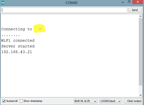
Connect the DOIT ESP32 Devkit to your computer, ensure it is selected as the board type on the Arduino IDE, then paste the code in the IDE, verify and upload. When the upload is finished open the serial monitor. You should see the IP address displayed as shown in the Image below.
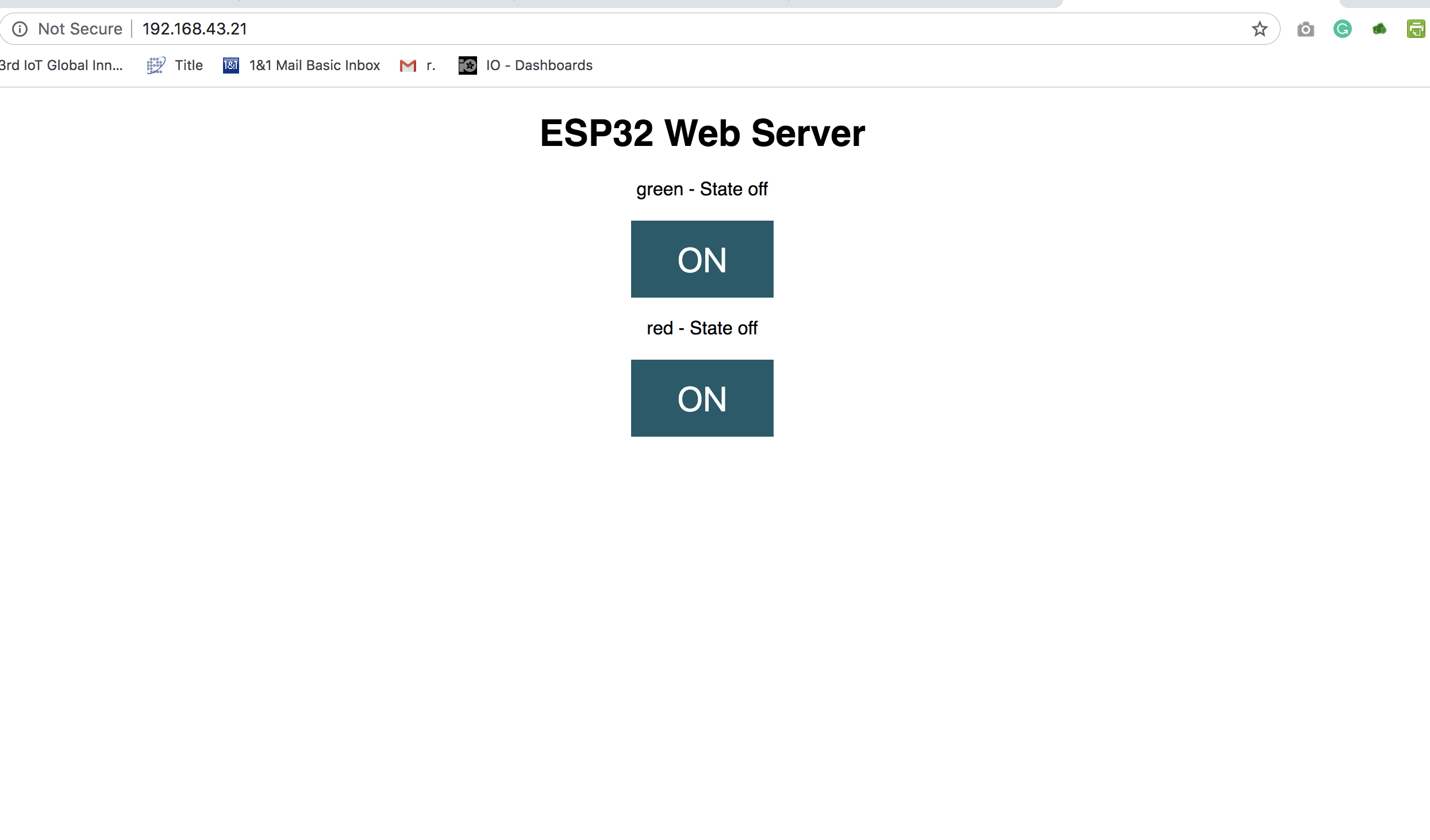
Connect a device (mobile phone or PC) to the same network as the ESP32, then open a web browser on that device and enter the IP address from the serial monitor in the Address bar. It should open the webpage we created on the web server as shown in the Image below. Click on the buttons to toggle the LEDs.
As mentioned earlier, in place of the LEDs, relays or any other kind of actuator could be connected to make the project more useful. Feel free to reach out to me via the comment section if you have any question on the tutorials.
Till next time.



Thank you
do you have part of eps32 on fritzing? Please share me. Thanks
Thanks for that. Steep learning curve.
I’m intrigued by the statement ” client.println(“green – State ” + greenstate + “”) ;” which appears to have a mix of text and variables. Is this just peculiar to client.println? or the ESP32?