Driving an 8×8 (64) LED Matrix with MAX7219 (or MAX7221) and Arduino Uno
- Nick Koumaris
- http://educ8s.tv
- info@educ8s.tv
- 32.387 Views
- easy
- Tested
Introduction
Hi guys, today we will be focusing on displaying mini graphics and texts on an 8×8 LED matrix using the MAX7219 (or MAX7221) LED driver and the Arduino Uno.
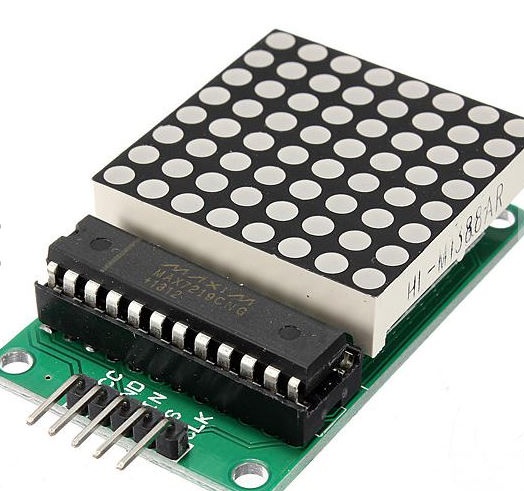
The 8×8 LED matrix displays are usually used for the display of symbols, simple graphics and texts. Made of super bright LEDs, they produce low resolution display and can be daisy chained to produce larger displays.
To enable us to control the display easily, we will be using the MAX7219/MAX7221 LED display driver module. Although this driver comes attached to the LED Matrix display that we will be using for this tutorial, its important to treat them separately, so you can understand how the LED driver works and be able to use it in case you are unable to get an 8×8 LED Matrix display that comes with the LED Driver.
The MAX7219/MAX7221 are compact, serial input/output common-cathode display drivers that interface to microcontrollers and microprocessors to control 7-segment numeric LED displays of up to 8 digits, bar-graph displays, or 64 individual LEDs. Included on the MAX7219 chip is a BCD code-B decoder, a multiplex scan circuitry, a segment and digit drivers, and an 8×8 static RAM that stores each digit. Only one external resistor is required to set the segment current for all LEDs. The MAX7221 is compatible with SPI, QSPI, and MICROWIRE communication protocols, and has slew-rate-limited segment drivers to reduce EMI. Individual digits of the connected LED display may be addressed and updated without rewriting the entire display. The MAX7219/MAX7221 also allow the user to select code-B decoding or no-decode for each digit.
Required Components
The components required for this project are;
Do note that the 8×8 LED matrix used in this tutorial already comes with the LED Driver attached as its common with most 8×8 LED modules these days. To get it, just follow the link attached to it.
Schematics
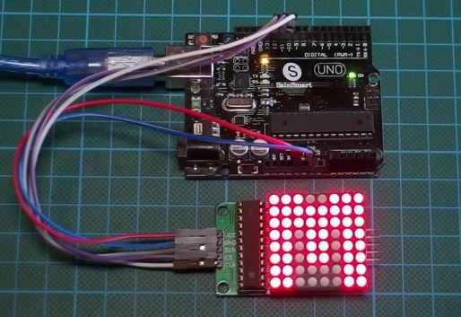
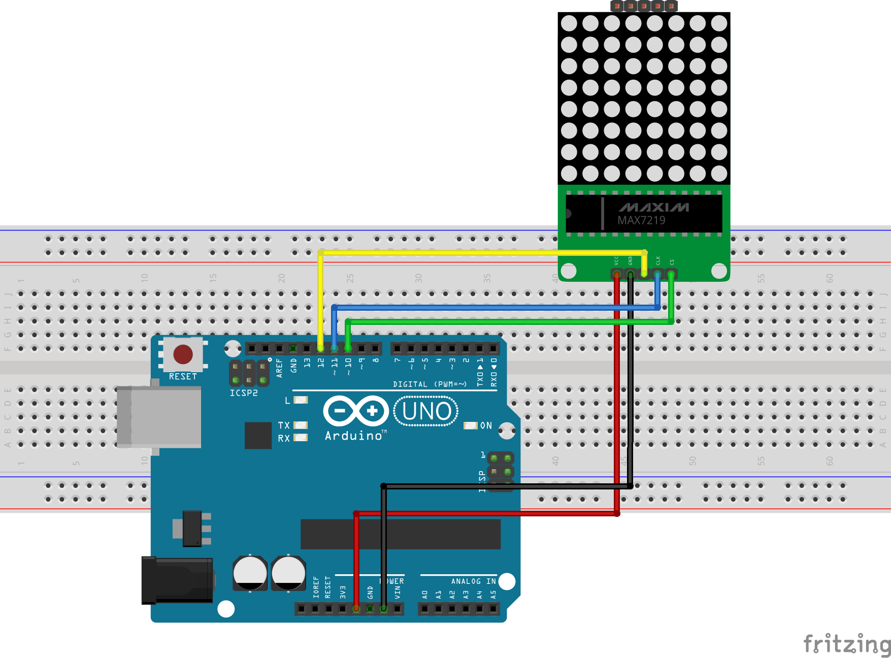
Connect the Module to the Arduino as shown in the Fritzing schematics below.
here is a pin map of the connection for clarity.
Display – Arduino
VCC  - 5V
GND - GND
DIN - D12
CS -  D11
CLK - D10
Creating Graphics for Display on the LED Matrix
Before we proceed to writing the code for this project, I would like to show you an easy way of creating the graphics to be displayed on the LED Matrix and generating the byte array that will be used in the code to represent the graphics to be displayed. To do this, we will use a very lightweight software which I found online, called “PixeltoMatrix”.
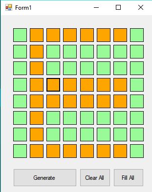
This software allows you draw your graphics by highlighting boxes like some dots connecting sort of game, then generates the byte array which you can then copy and use in your code.
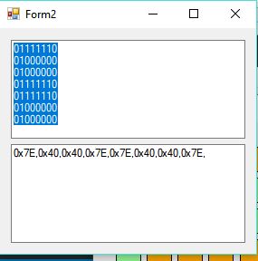
pretty cool right? I thought so too.
Code
To ensure ease of the coding process, we will use the LEDcontrol library which can be downloaded from here. This Library makes the process of programming the Arduino to drive the LED matrix easy. So as usual, download the library, extract it and copy to your Arduino libraries folder, then start the Arduino IDE.
The first thing we do in the code as usual, is to include the libraries that will be used, then we declare the pins on the Arduino to which the LED Matrix is connected.
//Written by Nick Koumaris
//info@educ8s.tv
//educ8s.tv
#include <LedControl.h>
int DIN = 12;
int CS =  11;
int CLK = 10;
After declaring the pins, we declare the byte arrays that describe the graphics to be displayed. The byte arrays were generated as described in the previous section. The first one, for instance, is the byte array to display a smile.
byte e[8]=     {0x7C,0x7C,0x60,0x7C,0x7C,0x60,0x7C,0x7C};
byte d[8]=     {0x78,0x7C,0x66,0x66,0x66,0x66,0x7C,0x78};
byte u[8]=     {0x66,0x66,0x66,0x66,0x66,0x66,0x7E,0x7E};
byte c[8]=     {0x7E,0x7E,0x60,0x60,0x60,0x60,0x7E,0x7E};
byte eight[8]= {0x7E,0x7E,0x66,0x7E,0x7E,0x66,0x7E,0x7E};
byte s[8]=     {0x7E,0x7C,0x60,0x7C,0x3E,0x06,0x3E,0x7E};
byte dot[8]=   {0x00,0x00,0x00,0x00,0x00,0x00,0x18,0x18};
byte o[8]=     {0x7E,0x7E,0x66,0x66,0x66,0x66,0x7E,0x7E};
byte m[8]=     {0xE7,0xFF,0xFF,0xDB,0xDB,0xDB,0xC3,0xC3};
After the byte arrays for the graphics to be displayed has been created, we then create an object of the LCD control library.
LedControl lc=LedControl(DIN,CLK,CS,0);
Next, we move to the void setup() part of the code. With the library lifting most of the heavy loads we don’t have much to do. The first thing we do in the loop section is call take the MAX7219 out of the power saving mode, then we set the brightness of the display using the lc.setintensity() function, after which we clear the display, making it ready to receive data.
void setup(){
 lc.shutdown(0,false);       //The MAX72XX is in power-saving mode on startup
 lc.setIntensity(0,15);      // Set the brightness to maximum value
 lc.clearDisplay(0);         // and clear the display
}
With this done, we then go to the void loop() function which featured some more declaration of graphics byte arrays, and the display of the graphics on the LED Matrix. The display of a graphics on the LED matrix is done via the function, printbyte(), with the argument of the function being the name of the byte array representing the graphics to be displayed. For example, printbyte(smile) prints the graphics “smile” as described by its byte array.
After displaying the graphics, the delay() function is used to keep the graphics on the LED matrix for a specific number of seconds.
void loop(){

    byte smile[8]=   {0x3C,0x42,0xA5,0x81,0xA5,0x99,0x42,0x3C};
    byte neutral[8]= {0x3C,0x42,0xA5,0x81,0xBD,0x81,0x42,0x3C};
    byte frown[8]=   {0x3C,0x42,0xA5,0x81,0x99,0xA5,0x42,0x3C};

    printByte(smile);

    delay(1000);
Every other part of the code is a slight modification to things we already know and is easy to follow.
The full Code for the project is available below and also attached in the zip file provided under the download section which can be found at the end of this post.
// Written by: Nick Koumaris
// educ8s.tv

#include <LedControl.h>

int DIN = 12;
int CS =  11;
int CLK = 10;

byte e[8]=     {0x7C,0x7C,0x60,0x7C,0x7C,0x60,0x7C,0x7C};
byte d[8]=     {0x78,0x7C,0x66,0x66,0x66,0x66,0x7C,0x78};
byte u[8]=     {0x66,0x66,0x66,0x66,0x66,0x66,0x7E,0x7E};
byte c[8]=     {0x7E,0x7E,0x60,0x60,0x60,0x60,0x7E,0x7E};
byte eight[8]= {0x7E,0x7E,0x66,0x7E,0x7E,0x66,0x7E,0x7E};
byte s[8]=     {0x7E,0x7C,0x60,0x7C,0x3E,0x06,0x3E,0x7E};
byte dot[8]=   {0x00,0x00,0x00,0x00,0x00,0x00,0x18,0x18};
byte o[8]=     {0x7E,0x7E,0x66,0x66,0x66,0x66,0x7E,0x7E};
byte m[8]=     {0xE7,0xFF,0xFF,0xDB,0xDB,0xDB,0xC3,0xC3};

LedControl lc=LedControl(DIN,CLK,CS,0);

void setup(){
 lc.shutdown(0,false);       //The MAX72XX is in power-saving mode on startup
 lc.setIntensity(0,15);      // Set the brightness to maximum value
 lc.clearDisplay(0);         // and clear the display
}

void loop(){

    byte smile[8]=   {0x3C,0x42,0xA5,0x81,0xA5,0x99,0x42,0x3C};
    byte neutral[8]= {0x3C,0x42,0xA5,0x81,0xBD,0x81,0x42,0x3C};
    byte frown[8]=   {0x3C,0x42,0xA5,0x81,0x99,0xA5,0x42,0x3C};

    printByte(smile);

    delay(1000);

    printByte(neutral);

    delay(1000);

    printByte(frown);

    delay(1000);

    printEduc8s();

    lc.clearDisplay(0);

    delay(1000);
}

void printEduc8s()
{
  printByte(e);
  delay(1000);
  printByte(d);
  delay(1000);
  printByte(u);
  delay(1000);
  printByte(c);
  delay(1000);
  printByte(eight);
  delay(1000);
  printByte(s);
  delay(1000);
  printByte(dot);
  delay(1000);
  printByte(c);
  delay(1000);
  printByte(o);
  delay(1000);
  printByte(m);
  delay(1000);
}

void printByte(byte character [])
{
  int i = 0;
  for(i=0;i<8;i++)
  {
    lc.setRow(0,i,character[i]);
  }
}
Demo
Upload the code to your Arduino board, you should see something like the image below.
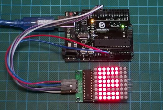
That’s it for this tutorial guys, don’t forget to leave questions, and comments, in the comments section of the tutorial.
Till next time, Keep Building!
The youtube video for this tutorial is available via the attached link, here




Hi.
Who want can use my online app.:
http://ilo.php5.sk/lcd84x48.htm
1. Set “Vlastná veľkosť tabuľky:” 8×8 and press tabxy.
2. Create char,symbol…
3. select MPLAB XC8 and press Assembler kód
4.Renam array,Copy and Past to your Arduino project