600V – 30A IPM Module Carrier Board for Variable Frequency Drive (VFD)
- Rajkumar Sharma
- 2.008 Views
- advanced
- Tested
- SKU: EL111343
- Quote Now
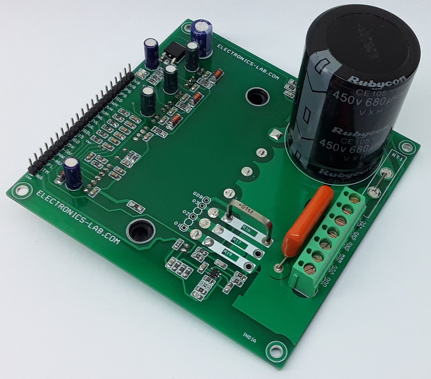
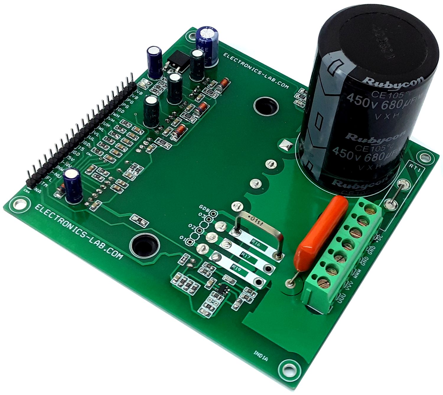
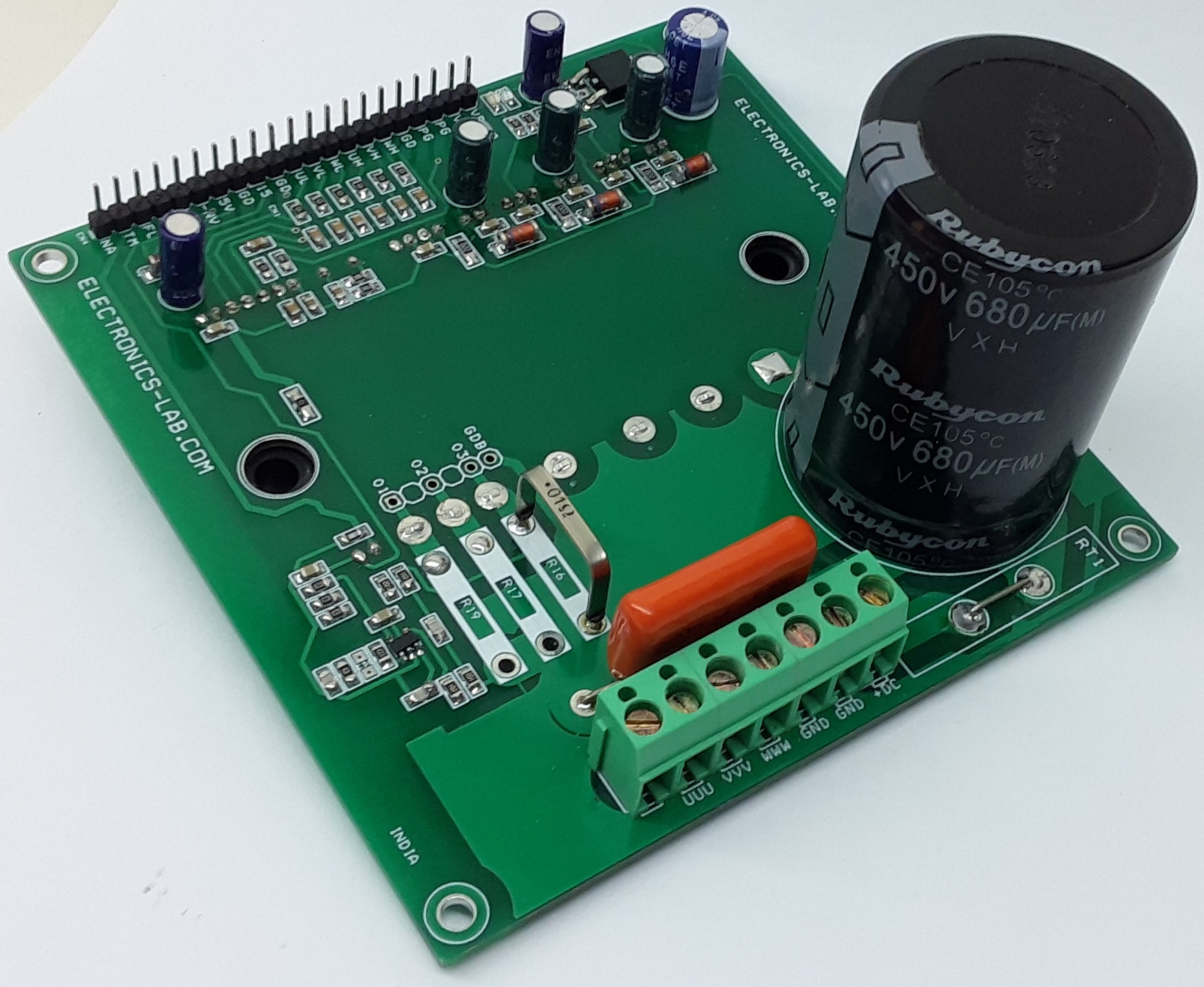
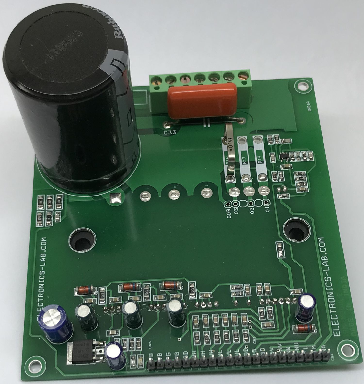
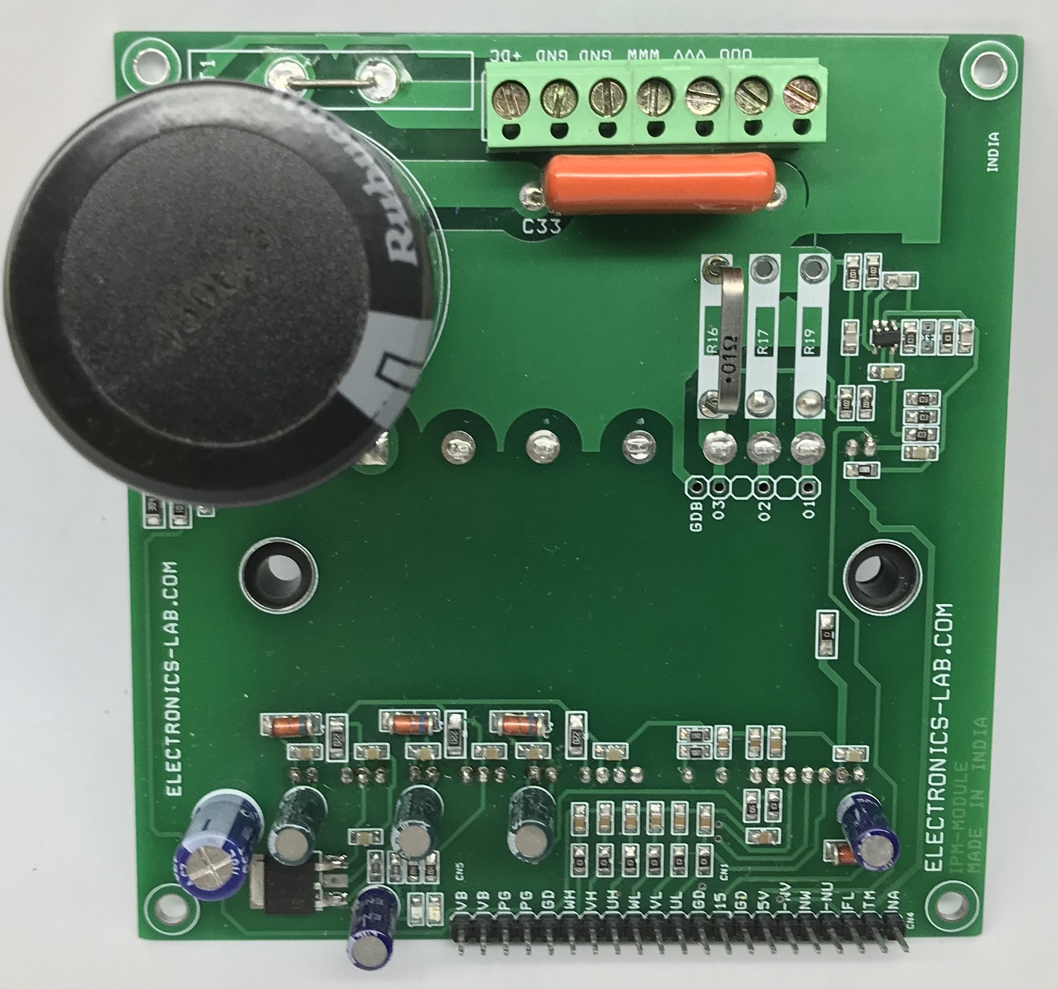
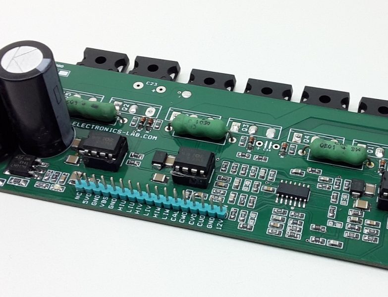
This compact IPM module circuit provides a fully-featured, high-performance inverter output stage for AC Induction, BLDC, and PMSM motors. The circuit is based on FNA23060 chip which integrates the optimized gate drive of the built-in IGBTs to minimize EMI and losses, while also providing multiple on-module protection features: under-voltage lockouts, over-current shutdown, temperature sensing, and fault reporting. The built-in, high-speed HVIC requires only a single supply of 15V and translates the incoming logic-level gate inputs to high-voltage, high-current drive signals to properly drive the module’s internal IGBTs. On-Board optional current sense circuit can be used to monitor the current. LM317 regulator provides 5V DC output to drive op-amp current sense circuit. LED D4 and D5 indicate 5V power and 15V power. Board has an option for 3 current sense resistors. An external 3 phase current circuit is required for 3 phase current sense circuit, if a single current sense circuit is required, solder all 3 phase NU+, NV+, NW+ together and use U4 op-amp circuit, in this case, solder R16. The current sense circuit is built using op-amp based, the gain of the circuit can be set as per user requirement. The board works with lethal high voltage DC and requires extra care while testing. PFC-based DC power supply is recommended to power the board.
Features
- Operating Supply Motor 90V to 390V DC
- IPM Load Current Maximum 30Amps (Approx. 2.2KW Motor Rating)
- Logic Supply 15V DC
- Motor Supply (Bus-Voltage Feed-Back Output 3.2V when Bus 390V, 0.75 when Bus V=90V)
- On-Board Current Sense Circuit
- Current Sense Output 1.7V at 0 Amp 100mV/Amp Approx.
- 2X Power LEDs for 15V and 5V
- Fault Output Normally High Goes Low When Fault Condition Occurs
- Over Current Circuit
- Under-Voltage Protection Circuit Detection Level 10.8-12.8V
- Short Circuit Current Level 60A
- Inbuilt Thermistor for over Temperature 47K Ohms @ 25 Degree Centigrade, 2.9K @ 100 Degree Centigrade
- Over Temperature Protection Output
- Operating Frequency up to 20Khz
- PCB Dimensions 100.17 x 104.93 mm
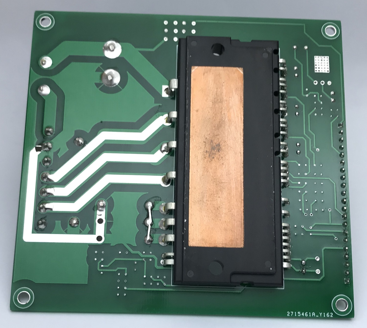
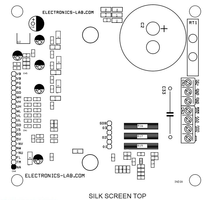
Current Sense: the board has provision to mount 3 shunt resistors if 3 phase current monitor is required, in this case, use R16, R17, R19 resistors. This will require 3 phase current to voltage op-amp circuit, the board has provision to measure a single current sense, in this case, solder all 3 emitters of IGBTs (Pin 5,6,7) and use U4 op-amp circuit to monitor the current of the motor.
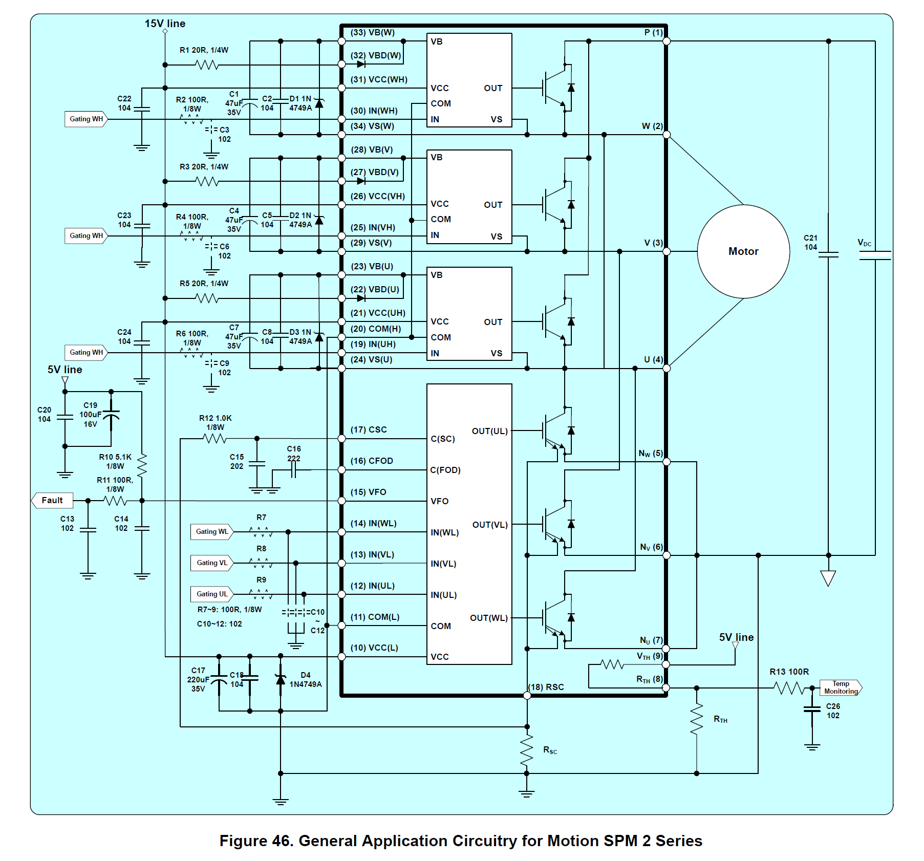
Over Current: The IPM module has an inbuilt separate over-current shutdown circuit, over-current is set using R23, R24, and C27, refer to datasheet of IC to calculate the Over Current shutdown threshold as per requirement.
Signal Input Pins: Pins IN(UL), IN(VL), IN(WL), IN(UH), IN(VH), IN(WH), These pins control the operation of the built−in IGBTs. They are activated by voltage input signals. The terminals are internally connected to a Schmitt−trigger circuit composed of 5 V−class CMOS. The signal logic of these pins is active HIGH. The IGBT associated with each of these pins is turned ON when a sufficient logic voltage is applied to these pins. The wiring of each input should be as short as possible to protect the Motion against noise influences. To prevent signal oscillations, RC (Resistors and capacitors) R1, R5, R6, R11, R12, R13, C3, C4, C5, C11, C12, C13) provided at all 6 inputs signals.
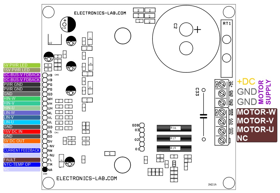
Power Supply: 15V DC supply required to drive the Logic gate driver circuit Use Pin 1and 2 of connector CN1 to apply logic supply. U2 LM317 regulator provides 5V DC to op-amp circuit for current sense. CN2 screw terminals are provided to power the load.
Power LED: D4 5V LED, D5 15V LED
Motor Supply Voltage Feedback: CN5 Connector provides Bus voltage (Motor Supply) feedback (Output 3.2V when 390V, 0.75V when Bus V=90V)
Motor Connections: 4 Pin screw terminal CN3 for motor connections, pin 1 motor phase W, pin 2 motor phase V, pin 3 motor phase U
Heatsink: Large size heatsink and fan is very important to cool down the IPM module.
Schematic
Parts List
| NO | QNTY. | REF. | DESC. | MANUFACTURER | SUPPLIER | SUPPLIERS PART NO |
|---|---|---|---|---|---|---|
| 1 | 1 | CN1 | 9 PIN HEADER MALE 2.54MM PITCH | WURTH | DIGIKEY | 732-5322-ND |
| 2 | 1 | CN2 | 3 PIN SCREW TERMINAL 5.08MM PITCH | PHOENIX | DIGIKEY | 277-1248-ND |
| 3 | 2 | CN3 | 2 PIN SCREW TERMINAL 5.08MM PITCH | PHOENIX | DIGIKEY | 277-1247-ND |
| 4 | 1 | CN4 | 8 PIN MALE HEADER 2.54MM PITCH | WURTH | DIGIKEY | 732-5321-ND |
| 5 | 1 | CN5 | 4 PIN MALE HEADER 2.54MM PITCH | WURTH | DIGIKEY | 732-5317-ND |
| 6 | 5 | C1,C7,C8,C10,C15, | 0.1uF/50V SMD SIZE 0805 | MURATA/YAGEO | DIGIKEY | |
| 5 | C17,C19,C22,C24,C32 | 0.1uF/50V SMD SIZE 0805 | MURATA/YAGEO | DIGIKEY | ||
| 7 | 1 | C2 | 680uF/450V ELECTROLYTIC | NICHICON | DIGIKEY | 493-7535-ND |
| 8 | 5 | C3,C4,C5,C11,C12, | 1KPF/50V SMD SIZE 0805 | MURATA/YAGEO | ||
| 4 | C13,C23,C25,C31 | 1KPF/50V SMD SIZE 0805 | MURATA/YAGEO | |||
| 9 | 3 | C6,C9,C16 | 33uF/50V ELECTROLYTIC | NICHICON | DIGIKEY | 493-16213-3-ND |
| 10 | 3 | C14,C28,C29 | 56PF/50V SMD SIZE 0805 | MURATA/YAGEO | ||
| 11 | 1 | C18 | 470uF/25V ELECTROLYTIC | NICHICON | DIGIKEY | 493-4907-3-ND |
| 12 | 2 | C20,C21 | 100uF/25V ELECTROLYTIC | NICHICON | DIGIKEY | 493-12902-1-ND |
| 13 | 2 | C26,C27 | 2K2PF/50V SMD SIZE 0805 | MURATA/YAGEO | ||
| 14 | 1 | C30 | OMIT | |||
| 15 | 1 | RT1 | JUMPER WIRE 2MM DIAMETER | GLOBAL SPECIALITEAS | DIGIKEY | BKWK-3-ND |
| 16 | 4 | D1,D2,D3,D6 | 22V/1W ZENER DIODE | VISHAY | DIGIKEY | ZM4748A-GS08TR-ND |
| 17 | 2 | D4,D5 | LED SMD SIZE 0805 | OSRAM | DIGIKEY | 475-1410-2-ND |
| 18 | 1 | R9 | 0E SMD SIZE 0805 | MURATA/YAGEO | DIGIKEY | |
| 19 | 4 | R1,R5,R6,R10, | 100E 5% SMD SIZE 0805 | MURATA/YAGEO | ||
| 4 | R11,R12,R26,R31 | 100E 5% SMD SIZE 0805 | MURATA/YAGEO | |||
| 20 | 3 | R2,R13,R15 | 22E 5% SMD SIZE 1206 | MURATA/YAGEO | ||
| 21 | 4 | R3,R4,R7,R8 | 300K 1% SMD SIZE 1206 | MURATA/YAGEO | ||
| 22 | 5 | R14,R29,R30,R35,R36 | 10K 5% SMD SIZE 0805 | MURATA/YAGEO | ||
| 23 | 1 | R16 | 0.01E | RIEDON | DIGIKEY | 696-1630-ND |
| 24 | 2 | R17,R19 | DNP | OMIT | OMIT | |
| 25 | 1 | R18 | 220E 1% SMD SIZE 0805 | MURATA/YAGEO | ||
| 26 | 1 | R20 | 680E 1% SMD SIZE 0805 | MURATA/YAGEO | ||
| 27 | 4 | R21,R22,R24,R27, | 1K 5% SMD SIZE 0805 | MURATA/YAGEO | ||
| 3 | R28,R33,R34 | 1K 5% SMD SIZE 0805 | MURATA/YAGEO | |||
| 28 | 1 | R23 | 33E 5% SMD SIZE 0805 | MURATA/YAGEO | ||
| 29 | 1 | R25 | 5K1 1% SMD SIZE 0805 | MURATA/YAGEO | ||
| 30 | 1 | R32 | 6K8 5% SMD SIZE 0805 | MURATA/YAGEO | ||
| 31 | 1 | U1 | FNA23060 | ON SEMI | DIGIKEY | FNA23060-ND |
| 32 | 1 | U2 | LM317 | ON SEMI | DIGIKEY | LM317MDTRKGOSCT-ND |
| 33 | 1 | U4 | MCP6001 | MICROCHIP | DIGIKEY | MCP6001RT-E/OTCT-ND |
Connections
System Diagram
Application Circuit
Block Diagram
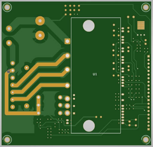
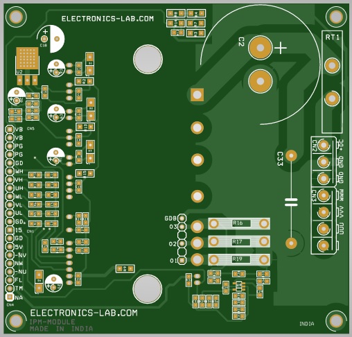
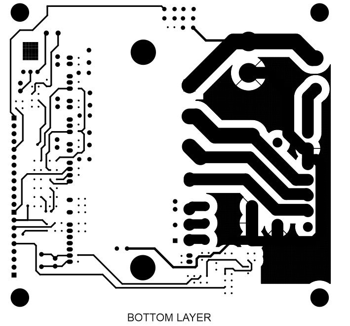
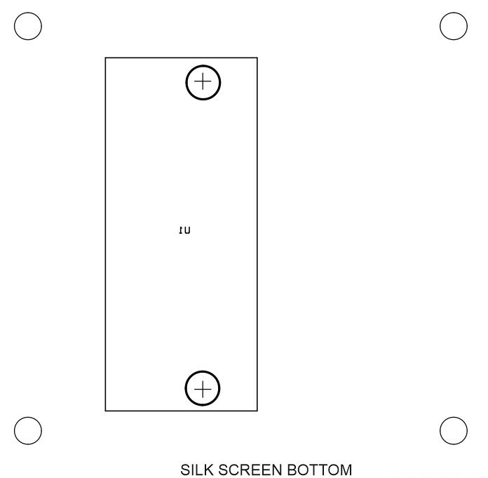
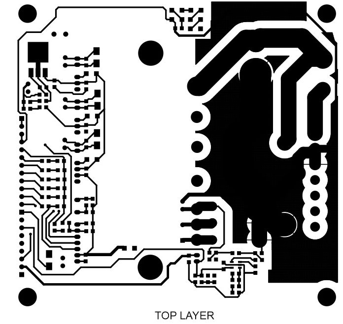
Gerber View
Photos
Video







I’m doing research on making a 3 phase controller using IPM ikcm15l60gd, I’m having trouble getting a max voltage of 48 on phase
do you have any suggestions for this problem, thank you for your attention